
Hykabaï
Table of Contents
- Hykabaï
- Table of Contents
Design Goal
The transport module was designed with the following characteristics in mind:
- Manufacturing
- Fast manufacturing
- Replicable
- Low cost
- Basic unit on a Fleet Management System (FMS)
- Optimized size for desktop manufacturing equipment
This 3D model shows the design of the robot, you can move it around to check some of it’s components.
Interactive 3D Model of Hykabaï, click and move it
This is the built robot, available at the Experimental Fabrication Laboratory (LabFabEx) at Universidad Nacional de Colombia.

Picture of Hykabaï
Name
Hykabaï means horse in Chibcha, one of the Colombian native languages, and given the similarities as transport, the name was adopted.
Mind Map
With these considerations, the following mind map was designed, aiming to provide a tree of possible options to different design arquitectures.

Mind Map of the Robot design
SDV
Likewise, the Self Driving Vehicle model was elected for navigation, instead of an Autonomous Guided Vehicle one, as the routing flexibility (capability of reordering the production steps) of the Microfactory would be the reduced with the second option, as well as the necessity of placing reference beacons or guidelines which would increase the implementation cost.
Design Characteristics
Hykabaï has the following Key Performance Indicators (KPI):

Hykabaï Key Performance Indicators
Axiomatic Design
Making use of the design tools offered by the Axiomatic Design proposed by Professor Suh, the fundamental variables of the robot are modeled in the Design Matrix A, which is visualized below, with which the functionalities required by the design are satisfied.
Given that this robot will reduce custom built components to replace with Commercial Off The Shelf (COTS) components, the axiomatic design on tihs robot was only applied up to matrix B, because manufacturing processes parameters will be reduced as much as possible.
Matrix A
| Requirement | ROS | Differential Configuration | LIDAR | PRIA Integrated | Containerized |
|---|---|---|---|---|---|
| Autonomous Driving | x | 0 | 0 | 0 | 0 |
| 360 degree movement | 0 | x | 0 | 0 | 0 |
| 360 degree perception | 0 | 0 | x | 0 | 0 |
| Lab Integrated | 0 | 0 | 0 | x | 0 |
| Replicable | 0 | 0 | 0 | 0 | x |
Matrix B
| Requirement | Raspberry Pi | Gearmotor | RPLIDAR A1 | TurtlePRIA | Docker |
|---|---|---|---|---|---|
| ROS | x | 0 | 0 | 0 | 0 |
| Differential Configuration | 0 | x | 0 | 0 | 0 |
| LIDAR | 0 | 0 | x | 0 | 0 |
| PRIA Integrated | 0 | 0 | 0 | x | 0 |
| Containerized | 0 | 0 | 0 | 0 | x |
Mechanical Design
Differential Configuration
Afterwards, the traction system was designed. The differential model allows turning over a point, in other words, the robot’s central axis perpendicular to the ground. This is important as it reduces space required for maneuvering in small areas, unlike the Ackermann model.

Kinematic Model of a Differential Robot
In this diagram we observe a line that crosses the wheels and the orientation line, that is the point mentioned beforehand. The kinematic model is described as follows:
\[\begin{bmatrix} x_k\\ y_k\\ \theta_k \end{bmatrix} = \begin{bmatrix} x_{k-1}\\ y_{k-1}\\ \theta_{k-1} \end{bmatrix} + \begin{bmatrix} \cos{\theta} & 0 \\ \sin{\theta} & 0 \\ 0 & 1 \end{bmatrix} \begin{bmatrix} \Delta s\\ \Delta \theta \end{bmatrix}\]And the robot velocities are:
\[\dot x=v \cos{\theta}\] \[\dot y = v \sin{\theta}\] \[\dot \theta = \omega\]Its maneuverability is : \(\delta_M = 2\) And it’s mobility degree is \(\delta_m=2\)
Materials
Due to the flexibility required by design purpose, multiple materials and manufacturing processes were taken into account when designing the robot, therefore the next figure shows manufacturing technologies in blue, and materials in orange.

Possible manufacturing methods and materials
Electronic Design
Boards
Due to the necessity of a high complexity task item and an integrated process two boards to execute each task group was selected. The first board is a Raspberry Pi 3B+, that works as the ROS Master node, as well as the LIDAR and task sequence execution. The second board is a BeagleBone Blue, another Single Board Computer (SBC) with a robotics cap integrated in it (DC Motor drivers, servo motors, IMU, etc.). This was done taking into account the OpenRoACH project and the University of Michigan MBot robot, with help of professor Peter Gaskell.
The Raspberry Pi 3B board is a 1GB RAM model, so it runs the high complexity processes considering that it has a higher RAM capacity and a quad-core Cortex-A53 processor. The operating system running corresponds to an adapted version of Debian Buster with ROS Melodic (This was used for the first model).
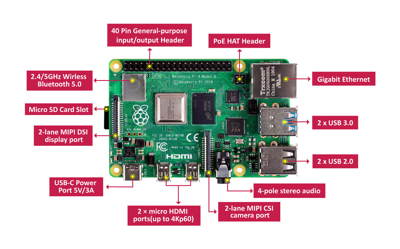
Raspberry Pi 4 Components
The Raspberry Pi 4 is a popular SBC used to implement Linux-based systems in robotics applications. There are multiple RAM size options, for Hykabaï, the 8GB RAM model was used.
The BeagleBone Blue houses a 1GHz Octavo OSD3358 microprocessor with 512MB DDR3 memory. It is running a modified version of Ubuntu MATE 18 (Bionic Beaver) by Robert C. Nelson, to include packages from the librobotcontrol library that provides C interface to the board’s perfs, such as input with qwiic connector for 4 encoders, two TB6612FNG drivers for DC motors, 9-axis IMU and a barometer, multiple SPI ports, UART and 8 servo motor outputs. The board has a balance connector for 2-cell LIPO batteries (7.4V).

BeagleBone Blue SBC Components
The BBBlue has two TB6612FNG dual motor drivers, and are controlling two Pololu 78:1 Metal Gearmotor 20Dx43L mm 6V. As well, the board is powered by a 2S 1000mAh battery, that connects directly with the balance port to the on-board connector.
The components of the BeagleBone Blue used are:
| Name | Component | Usage |
|---|---|---|
| 9 Axis IMU and Barometer | IMU | Velocity, Acceleration and Orientation perception |
| TI Wilink 8 | Wifi and Bluetooth Chip | Wireless Communication |
| USB Host | USB Connector | Connection with Raspberry Pi |
| 2 Cell LiPo Battery Connector | LiPo Battery Connector | Motor Voltage Sourcing |
| Octavo Systems OSD3358 | Microprocessor System-in-Package | Motor and Encoder Control |
| DC Motor Drivers | Motor Drivers | Moving the Motors |
| Quadrature Encoder | Encoder Connectors | Read the Encoder Sensors |
Encoders
The encoders are using Enhanced Quadrature Encoder Pulse (eQEP) to read both magnetic encoders. The encoders for 20D motors were selected. They count with an operating voltage of 2.7V up to 18V. It consists of a dual channel Hall effect sensor board, and a 10-pole magnetic disk. These are incremental encoders.

Encoder selected
This encoder reports a 20 Count Per Revolution, yet as seen in the following image, the number of pulses (or Pulse Per Revolution, PPR), is 4 times the amount of CPR’s. The following figure represents the reading of an incremental encoder.

How an encoder reads data
\(1 CPR = 4PPR \\\) \(20 CPR = 80 PPR\)
The absolute encoder instead measures the absolute position, and every step is predefined by a unique set of values combined, in the next image provided by RealPars, we can observe how this type of encoder works.

How an absolute encoder works
Furthermore, taking into account the reductor on the Gearmotor, and the diameter of the wheel, the equivalency between distance traveled by the wheel and the CPR’s by the encoder is given by:

Diagram of the revolutions across de traction system
\[\frac{Wheel \, Perimeter}{Encoder \, CPR \cdot N \, Relation}\]With the position update thanks to the equations in the differential configuration kinematic model, the robot recognizes its current position. Nevertheless, the dead reckoning method used ignores errors caused by sliding wheels on the floor, causing an error accumulation over time. To solve this issue, Gyrodometry was implemented. Gyrodometry is an algorithm that fuses odometry percieved by encoders and Inertial Unit Measurement (IMU) odometry. This error reduces up to 8 times the error generated by dead reckoning. Gyrodometry is defined as follows:
\[\Delta \theta_g = \begin{cases} \Delta \theta_{IMU} &\quad\text{if } \Delta \theta_{th} < \theta_o\\ \Delta \theta_{o} &\quad\text{if } \Delta \theta_{th} > \theta_o\\ \end{cases}\]Where \(\theta_o\) is the odometry due to the encoders, and \(\theta_{IMU}\) is the one by the IMU.
There was an error identified where the robot drifts towards the left side of the robot, in order to solve this issue an statistc evaluation of the ticks recorded on a turn command were analyzed. In next figure you can see the graph of the difference in the ticks recorded and there is a constant proportional value, so the average error was used to find a constant value to multiply the left wheel velocity command.

Encoder Correction
Electrical Design
Battery
For the Raspberry Pi, any 5V, 2A or greater current will be enough to power the board. The current model uses an Adata P10000QCD such as the one represented in the image.
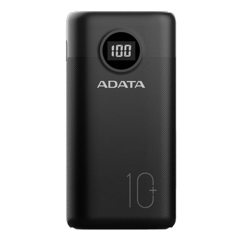
Example of a power bank
As for the BeagleBone Blue, the board supports using a 2S (2 Cell battery) directly trough its connector. There are multiple storage capacity presentations, this design uses 1000mAh by Turnigy.
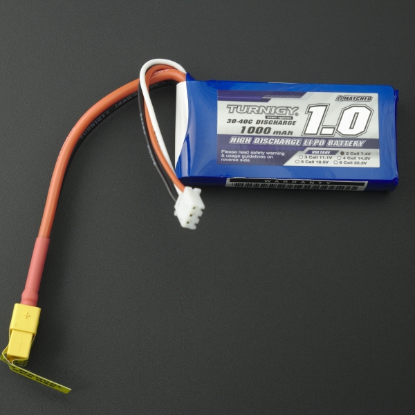
LiPo Battery
Motors
Two 78:1 Metal Gearmotor 20Dx43L mm 6V were selected. They have a 78:1 reduction ratio, operate on 6V and count with an extended motor shaft. The maximum speed is 180 rpm under no load, and a 2.4 kg-cm peak torque.
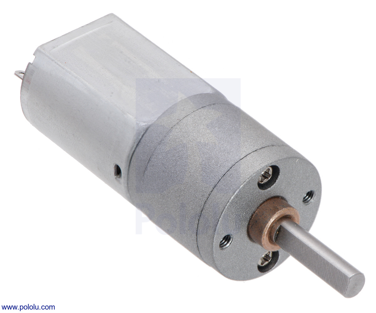
Image of the Pololu motors used
The manufacturer provides the following graph for it’s rpm, current consumption and eficciency. The robot works only at 0.6 m/s therefore, the efficiency is around the midpoint of it’s maximum, given that this linear speed has a lower load on the drivers, and allows for a soft movement profile.

Motor Efficiency Diagram
Connections
The electrical diagram the connections is the following:
As a simpler diagram the following image illustrates the connections that should be perfomed.

Electrical Connections
Assembly
As for the assembly here is shown the assembly process for the Hykabaï V1, a prototype designed for the Manufacturing Processes Automation class at UNAL.

Assembly of Hykabaï
The second assembly corresponds to the actual robot at the lab. It also has the same colors as seen in the first part of the page.

Assembly of the actual Hykabaï robot
Here we can see the robot in two subassemblies, the upper chassis where the Raspberry Pi and RPLidar are located, and the inferior one.
Some of the tools required to assemble the robot are:
-
Screwdriver (the tip depends on the screws for your robot) for each screw type. This robot used three, one for M3 screws, one for the motor, and one for the LiDAR M2 screws.
-
Pliers, to block the nut from moving when fastening the screw (embedded nuts could be used while manufacturing the base)
-
Soldering Iron (to solder the motor and encoder wires)
-
Soldering Paste (For a better soldering quality)
-
Multimeter, to check continuity while soldering the pins
The inferior chassis holds both motors and the BeagleBone Blue. Motor supports can be placed over or under the base. It is recommended to screw the motor supports to the base first. Either plastic or metallic screws can be used, Hykabaï uses M3 screws and nuts to fix the supports. It is recommended to build this subassembly first.

This is the base of the inferior chassis. The holes are to pass the motor and encoder wires, and to fix the battery strap if it is planned to be located at the bottom.
Inferior chassis base
And this is the motor support:
Motor support
This is the second version of the support design, as the first one failed due to the load, and broke trough the motor fastener holes, new versions are welcome to improve its life cycles. If the wheels are not parallel to each other,(check Troubleshooting), the motor supports may be too weak for your robot’s weight or payload.
The superior chassis is better built by mounting the Raspberry Pi and the superior base first, and the other components afterwards. The RPLiDAR uses M2 screws, insted of M3 ones, therefore either it’s standoffs must be changed, or M2 screws should be used. Height of the RPLiDAR may be adjusted as the robot’s enviroment changes.

Assembly of the superior components
Model of the superior base
| :— | Adapter-integrated Wheel | Bottom Base | Upper Base | Motor Support | LiDAR Support | Bottom Board Support | Upper Board Support | Free-Wheel | Motor | Encoder |
|---|---|---|---|---|---|---|---|---|---|---|
| Adapter-integrated Wheel | x | 0 | 0 | 0 | 0 | 0 | 0 | 0 | 1 | 0 |
| Bottom Base | 0 | x | 0 | 1 | 0 | 1 | 0 | 1 | 0 | 0 |
| Upper Base | 0 | 0 | x | 0 | 1 | 0 | 1 | 0 | 0 | 0 |
| Motor Support | 0 | 1 | 0 | x | 0 | 0 | 0 | 0 | 1 | 0 |
| LiDAR Support | 0 | 0 | 1 | 0 | x | 0 | 0 | 0 | 0 | 0 |
| Bottom Board Support | 0 | 1 | 0 | 0 | 0 | x | 0 | 0 | 0 | 0 |
| Upper Board Support | 0 | 0 | 1 | 0 | 0 | 0 | x | 0 | 0 | 0 |
| Free-Wheel | 0 | 1 | 0 | 0 | 0 | 0 | 0 | x | 0 | 0 |
| Motor | 1 | 0 | 1 | 0 | 0 | 0 | 0 | 0 | x | 1 |
| Encoder | 0 | 0 | 0 | 0 | 0 | 0 | 0 | 0 | 1 | x |
Software Design
Install Steps
- Installing OS on the Single Board Computers.
- Install Debian Buster on the Raspberry Pi using RPi Imager. Instructions on how to install it can be found here.
- Install ROS Melodic from source Use the sources for ros from Seedstudio
- Clone the BeagleBone Blue OS using this command or install it trough this image. If installed by yourself don’t forget to configure ROS_IP, ROS_MASTER_URI and all packages. Also use this fork for the motor drivers
- Install RPLidar
- Configure the serial port and use the following package
- Check using the following commands:
ls -l /dev/ |grep ttyUSBto check the correct connection andsudo chmod 666 /dev/ttyUSB0to give the required permissions
- Install Hykabaï packages
- For the general robot
- For simulation
- For mapping
- For navigation
Installation of these packages can be done using Windows or Debian OS, and each SBC requires a microSD card, at least 16gb is required, but 32gb is recommended.
Block diagram
Currently the mechatronic system of the robot works as following:

Block diagram of the Mechanical, Electrical and Communication systems
The Powerbank, provides energy for the Raspberry Pi, which connects to the RPLidar A1 via microUSB port and serial communication, and to the BeagleBone Blue via USB. This connection uses the USB port as a virtual ethernet port, assigning the 192.168.7.1 IP address to the RPi, and 192.168.7.2 address to the BeagleBone. Afterwards, to move the motors, the topics ran in the RPi (that is executing the ROS Master node), are captured by the bbdrivers package in the BeagleBone. This package implements directly the rc_library files to both, capture the encoder readings, and send movement signals to the motor drivers. As a side note, the robot is capable of executing all of the program without feeding the BeagleBone with it’s power supply (a 2S Lipo board in this case, using the balance port) yet it won’t be able to move.
Control
The robot uses multiple control options, whether it’s using our own PID controller for speed and position control, or integrated using the ROS Control package.
On/Off Control
Initally, to verify that the robot is moving the wheels accordingly to the direction it’s given, a simple order-two system was modeled to identify possible values for a speed controller, directly on the bbdrivers package. It was done to model the following control sequence.

On-Off control design
Two types of pulses were analyzed, in order to contrast if the perceived position due to odometry was correct, first, an angular speed pulse. A python node was coded to send pulses of an specific speed command, alternating between a top value and 0, to check the hardware’s ability to follow it. (Given it’s differential architecture, the speed considers the wheels turning in different directions simultaneously).

Speed pulses Designed vs Experimental
And afterwards, only linear speed pulses were analyzed.

Theoretical vs Experimental Linear Velocities
ROS
ROS is a communication framework to connect nodes that execute tasks, such as moving a motor, locating the robot or sending a goal, with other nodes through a topic, which is the name of the channel where certain message types, such as images, veloctities or point clouds are transferred.
The nodes running on the robot when performing mapping with Hector SLAM algorithm is presented in the next image, using RQT, a common graph tool for nodes and topics in ROS.

RQT Graph of the mapping process
The robot is communicated with PRIA UN using the following architechture, where the ROS Logic uses the generic PRIA package to communicate with an action server, and the robot locally uses the same nodes mentioned before. For more information on the connection in the Lab network visit this link

Integration in PRIA
The robot can be observed navigating in a square trajectory, simulating tranport between the modules of the microfactory, it is done using a PI controller to follow a predefined n-sided figure, and scale-adjusted as the user may need. The square figures show the placement where the other modules may be placed.

Hykabaï executing trajectories
The route the robot uses to know when to be activated and start a transportation routine is described in the following Process Oriented Analysis (POA) diagram, where the central section illustrates the inner Hykabaï workings, and in the exterior area, it’s integration with a PCB Microfactory manufacturing process.

Process Oriented Analysis Diagram of the robot
Testing
The robot has multiple operational modes.
To Turn on the Robot:
- Place the battery or strap it
- Turn on the Raspberry Pi, with the BBBlue disconnected, and the RPLidar connected to the Raspberry with microUSB cable
- Wait for the VNC connection
- Configure the RPlidar
- Connect the BBlue using the USB Cable
- Launch roscore and test the RPlidar
- Connect the LiPo battery to the BBBlue
For the VNC Server this is the data you need (using a local network):
User:pi Password:raspi
And to check the IP Address, connect it once to a display and execute ifconfig. The WLAN
To launch mapping using HectorSlam node by node do this:
- Execute
roscore - Execute
roslaunch rplidar_ros rplidar.launch- Execute
ls -l /dev/ |grep ttyUSB(to check usb) - Execute
sudo chmod 666 /dev/ttyUSB0 - Execute
roslaunch rplidar_ros view_rplidar.launch(if you want to verify it’s working)
- Execute
- Execute
rosrun bbblue_drivers vel_control_odom(on the BBBlue) - Execute
roslaunch hykabai_simulations rviz.launch(load config on hector_slam_launch folder) - Execute
roslaunch hector_slam_launch tutorial.launch
To run HectorSLAM with Launch
- Config RPLidar
- Execute
ls -l /dev/ |grep ttyUSB(check usb) - Execute
sudo chmod 666 /dev/ttyUSB0
- Execute
- Execute
rosrun bbblue_drivers vel_control_odom( on BBBlue)- Execute
roslaunch hector_slam hykabai_hector_slam.launch - Navigate using
rosrun teleop_twsit_keyboard teleop_twist_keyboard.py, at a 0.104 linear speed
- Execute
- When you’re satisfied with the map, execute
rosrun map_server map_saver
To shut down the robot:
First use Ctrl+C in all the terminals running, then:
- Execute
sudo shutdown nowin the BBBlue (sudopassword is temppwd) - Execute
sudo shutdown nowin the RPi.
Troubleshooting
If the robot is operating incorrectly, or issues are identified, the following FMECA analysis is presented, and the recommended solution for each case.