FPGA Servo Motor Control with VGA Display
Advanced FPGA project implementing servo motor position control with real-time VGA visualization using Verilog HDL on Altera Cyclone IV
FPGA Servo Motor Control with VGA Display
Overview
Advanced FPGA project implementing servo motor position control with real-time VGA visualization using Verilog HDL on Altera Cyclone IV
Project Overview
This advanced digital electronics project implements a sophisticated servo motor control system with VGA visualization using an Altera Cyclone IV FPGA. Developed as the final project for the Digital Electronics I course at Universidad Nacional de Colombia, it demonstrates the practical application of HDL programming, state machines, timing control, and hardware interfacing.
The system uses a finite state machine to control servo motor position based on DIP switch inputs, with the ability to set precise angles (0°, 30°, 45°, 90°). The VGA interface provides real-time visual feedback of the system state through color-coded displays.
Key Achievements
- Precise PWM Control: 20ms period servo control with 20ns resolution
- State Machine Implementation: DIP switch-driven position control
- VGA Driver: Custom RGB111 video signal generation at multiple frequencies
- Hardware Validation: Extensive testing across multiple VGA monitors and configurations
Technical Background
Servo Motor Control Theory
Conventional servo motors are controlled via Pulse Width Modulation (PWM), where the pulse width corresponds to angular position:
- Minimum Position (0°): 1ms pulse width = 50,000 clock cycles @ 50MHz
- Maximum Position (180°): 2ms pulse width = 100,000 clock cycles @ 50MHz
- Period: 20ms (standard servo control frequency)
With a 50MHz FPGA clock:
- Each tick = 1/50,000,000 Hz = 20ns
- 20ms period = 1,000,000 ticks
- Requires 20-bit counter:
[19:0](2^20 = 1,048,576)
PWM Timing Calculations
Angle Mapping:
• 0°   → 50,100 ticks  (1.002ms)
• 30°  → 58,333 ticks  (1.167ms)
• 45°  → 62,500 ticks  (1.250ms)
• 90°  → 75,000 ticks  (1.500ms)
• 180° → 100,000 ticks (2.000ms)
Implementation
Architecture Overview
The project consists of three main components:
- Servo Control Module - PWM generation and position management
- State Machine - DIP switch input processing
- VGA Driver - Video signal generation for visual feedback
Servo Motor Control
The servo control algorithm implements a 20-bit counter that cycles through 1,000,000 states to create the 20ms period. The servo signal stays HIGH for a duration determined by the selected angle, then goes LOW for the remainder of the cycle.
always @(posedge mclk) begin
    // 20ms period counter
    counter <= counter + 1;
    if(counter == 'd999999)
        counter <= 0;

    // PWM signal generation
    if(counter < ('d50000 + control))
        servo_reg <= 1;
    else
        servo_reg <= 0;
end
State Machine Design
The DIP switch state machine provides four discrete angular positions. Each switch combination maps to a specific servo angle:
| DIP Switch | Binary | Angle | Pulse Width |
|---|---|---|---|
| Position 0 | 3'b000 |
0° | 1.002ms |
| Position 1 | 3'b111 |
30° | 1.167ms |
| Position 2 | 3'b110 |
45° | 1.250ms |
| Position 3 | 3'b100 |
90° | 1.500ms |
The state machine reads the DIP switch configuration on each clock cycle and adjusts the PWM duty cycle accordingly, providing smooth transitions between positions.
VGA Driver Implementation
The VGA driver generates standard video timing signals for 640x480 @ 60Hz resolution (RGB111 format - 1 bit per color channel).
VGA Timing Parameters:
- Horizontal: 640px visible + 16px front porch + 96px sync + 48px back porch = 800px total
- Vertical: 480px visible + 10px front porch + 2px sync + 33px back porch = 525px total
- Pixel Clock: 25.175 MHz (generated from 50MHz using ALTPLL)
- Refresh Rate: 60Hz
The driver uses two counters (countX and countY) to track pixel position and generate appropriate sync pulses:
assign Hsync_n = ~((countX >= SCREEN_X + FRONT_PORCH_X) &&
                  (countX < SCREEN_X + SYNC_PULSE_X + FRONT_PORCH_X));

assign Vsync_n = ~((countY >= SCREEN_Y + FRONT_PORCH_Y) &&
                  (countY < SCREEN_Y + FRONT_PORCH_Y + SYNC_PULSE_Y));
Hardware Setup
FPGA Board: Altera Cyclone IV
The project uses the A-C4E10 development board featuring:
- FPGA: EP4CE10E22C8N (10,320 logic elements)
- Memory: 414kB embedded
- Clock: 50MHz internal oscillator
- I/O: 28 GPIO pins
- Interfaces: VGA RGB111 port, 8-position DIP switch, LEDs
- Programming: USB Blaster via JTAG
Clock Generation
The FPGA’s internal 50MHz clock is divided using Intel’s ALTPLL (Phase-Locked Loop) IP core to generate various frequencies for VGA testing:
- 20 MHz, 25 MHz, 30 MHz, 35 MHz
- 45 MHz, 50 MHz, 60 MHz, 75 MHz
- 130 MHz, 135 MHz
The ALTPLL was configured and tested at each frequency to determine optimal VGA compatibility across different monitors.
VGA Connection
The board’s RGB111 VGA port outputs 1-bit color per channel (8 colors total):
assign VGA_R = data_RGB444[11];  // Red MSB only
assign VGA_G = data_RGB444[7];   // Green MSB only
assign VGA_B = data_RGB444[3];   // Blue MSB only
This configuration was chosen to simplify the design while maintaining basic color visualization capabilities.
Testing & Validation
VGA Display Testing
Extensive testing was performed across 5 different VGA monitors:
- Syncmaster 3 - Basic VGA compatibility
- Syncmaster 917v3 - Standard resolution testing
- Syncmaster 2233SN - Modern LCD display
- Philips 150S4 - Compact monitor
- Panasonic Panablack TV - Tested via VGA→RCA and VGA→HDMI→RCA adapters
Clock Frequency Testing
Each monitor was tested with 10 different clock frequencies to determine optimal timing:
Tested Frequencies: 20, 25, 30, 35, 45, 50, 60, 75, 130, 135 MHz
Signal Verification
Hardware validation included:
- Clock Signal: Verified 50MHz FPGA clock output using oscilloscope
- VGA Pinout: Tested voltage levels on Green channel (largest screen area coverage)
- PWM Output: Confirmed servo control signal timing with oscilloscope
- Port Integrity: Verified VGA connector functionality
Challenges & Solutions
VGA Display Issues
Problem: Despite correct timing implementation and signal verification, no video output was visible on any tested monitor.
Investigation Steps:
- ✅ Verified clock divider functionality (oscilloscope)
- ✅ Confirmed voltage on VGA green pin (~0.7V)
- ✅ Tested multiple monitors and cables
- ✅ Tried various clock frequencies (20-135 MHz)
- ✅ Verified FPGA pin assignments
Conclusion: The VGA timing implementation follows industry standards, and hardware signals are correct. The issue may be related to:
- Specific monitor compatibility requirements
- Impedance matching on VGA lines
- Additional handshaking signals not implemented
- Minor timing variations outside tested configurations
Resource Optimization
Challenge: Limited FPGA resources (414kB memory)
Solution:
- Eliminated RAM buffer requirement by using direct color generation
- Simplified to RGB111 (3-bit color) instead of RGB444
- Removed camera capture module from original project template
- Used efficient state machine for servo control
Technical Specifications
System Parameters
| Parameter | Value |
|---|---|
| FPGA Clock | 50 MHz |
| Servo PWM Period | 20 ms |
| PWM Resolution | 20 ns (50 MHz) |
| Counter Width | 20 bits |
| Servo Range | 0° - 180° |
| Position States | 4 (0°, 30°, 45°, 90°) |
| VGA Resolution | 640×480 @ 60Hz |
| VGA Color Depth | RGB111 (8 colors) |
| Pixel Clock | 25.175 MHz |
Pin Assignments (Cyclone IV)
Servo Control:
- PWM Output → GPIO Pin
- DIP Switch[2:0] → Input Pins [8:6]
- LED[2:0] → Output Pins [13:11]

VGA Interface:
- Hsync → VGA Pin 13
- Vsync → VGA Pin 14
- Red → VGA Pin 1
- Green → VGA Pin 2
- Blue → VGA Pin 3
- GND → VGA Pins 5,6,7,8,10
Learning Outcomes
This project provided hands-on experience with:
- HDL Programming: Advanced Verilog coding for hardware description
- Timing Analysis: Critical understanding of clock cycles and signal timing
- State Machines: Implementing FSMs for control logic
- PWM Control: Precise servo motor positioning via pulse width modulation
- Video Standards: VGA timing protocol and synchronization signals
- FPGA Tools: Quartus Prime workflow, ALTPLL IP core, pin assignment
- Hardware Debugging: Oscilloscope verification and signal integrity testing
- Digital Design: Register management, counter design, and synchronous logic
Software Tools
Development Environment
- Intel Quartus Prime Lite Edition 20.1.1
- Verilog synthesis and compilation
- ALTPLL IP core for clock generation
- Pin Planner for I/O assignment
- TimeQuest timing analyzer
- USB Blaster programming interface
- ModelSim-Intel FPGA Starter Edition
- Verilog simulation and testbenches
- Waveform analysis
- Timing verification
Project Structure
entrega-final-2021grupo03/
├── ServoTest/          # Servo motor test module
├── SwitchTest/         # DIP switch state machine test
├── hdl/
│   ├── scr/            # Main source files
│   │   ├── test_VGA.v
│   │   ├── VGA_Driver640x480.v
│   │   ├── buffer_ram_dp.v
│   │   └── FSM_game.v
│   └── quartus/        # Quartus project files
├── scr/                # Additional source files
│   └── PLL/            # Clock generation modules
└── images/             # Documentation images
Future Enhancements
Potential improvements for this project:
- Advanced Servo Control: Implement continuous angle adjustment via analog input
- VGA Resolution: Support higher resolutions (800×600, 1024×768)
- True Color: Upgrade to RGB444 or RGB888 for richer color display
- Graphics Generation: Add sprite rendering and geometric shape drawing
- Camera Integration: Implement original video capture and display plan
- Motion Control: Multi-servo coordination for robotic arm applications
- UART Communication: Add PC interface for remote control
- Display Feedback: Show real-time servo angle on VGA display
- Position Memory: Store and replay servo movement sequences
Project Team
Contributors
Alejandro Ojeda Olarte
Role: Hardware implementation, servo control, VGA driver development
Juan José Herrera Rodríguez
Role: State machine design, testing, validation, documentation
Course Information
Institution: Universidad Nacional de Colombia
Course: Electrónica Digital I (Digital Electronics I)
Instructor: Prof. Ferney Alberto Beltrán Molina
Semester: 2021-2
Project Type: Final course project
References
Keywords
FPGA Verilog Cyclone IV Servo Motor PWM VGA Digital Electronics State Machine HDL Embedded Systems Quartus Prime ALTPLL Hardware Design Video Signal Finite State Machine
License
This project was developed for educational purposes as part of the Digital Electronics I course at Universidad Nacional de Colombia. The code and documentation are available under the course’s academic guidelines.
Repository: GitHub - entrega-final-2021grupo03
Code Files
Servo Motor Test
`timescale 1ns / 1ps

module ServoTest(
    input mclk,
    input [2:0] i_DipSw,
    output reg [0:2] o_LED,
    output servo
);

// 50 MHz clock onBoard
// 20 ms counter period
// 1/50,000,000 Hz = 20 ns (every posedge)
// (20,000,000 ns)/(20 ns) = 1,000,000
// (20 bits) (2^(20)-1) = 1,048,575

// Servo parameters
// Min (0 deg): 1 ms = 50,000*20ns
// Max (180 deg): 2 ms = 100,000*20ns

reg [19:0] counter = 0;
reg [15:0] control = 0;
reg        servo_reg;
reg        toggle = 1;
reg [1:0]  ledval = 0;

always @(posedge mclk) begin
    case (i_DipSw)
        3'b000: ledval = 0;  // 0 degrees
        3'b111: ledval = 1;  // 30 degrees
        3'b110: ledval = 2;  // 45 degrees
        3'b100: ledval = 3;  // 90 degrees
        default: ledval = 0;
    endcase

    // Counter for 20ms period
    counter <= counter + 1;
    if(counter == 'd999999)
        counter <= 0;

    // Position control based on DIP switch state
    if(ledval == 0)
        if(counter < ('d50100))  // 0 degrees
            servo_reg <= 1;
        else
            servo_reg <= 0;

    if(ledval == 1)
        if(counter < ('d58333))  // 30 degrees
            servo_reg <= 1;
        else
            servo_reg <= 0;

    if(ledval == 2)
        if(counter < ('d62500))  // 45 degrees
            servo_reg <= 1;
        else
            servo_reg <= 0;

    if(ledval == 3)
        if(counter < ('d75000))  // 90 degrees
            servo_reg <= 1;
        else
            servo_reg <= 0;
end

assign o_LED[0] = toggle;
assign servo = servo_reg;

endmodule
VGA Driver
module VGA_Driver640x480 (
    input rst,
    input clk,                    // 25MHz for 60Hz at 640x480
    input  [11:0] pixelIn,        // RGB444 pixel input
    output [11:0] pixelOut,       // RGB444 pixel output to VGA
    output Hsync_n,               // Horizontal sync (negative)
    output Vsync_n,               // Vertical sync (negative)
    output [9:0] posX,            // Horizontal pixel position
    output [8:0] posY             // Vertical pixel position
);

// VGA 640x480 @ 60Hz timing parameters
localparam SCREEN_X = 640;
localparam FRONT_PORCH_X = 16;
localparam SYNC_PULSE_X = 96;
localparam BACK_PORCH_X = 48;
localparam TOTAL_SCREEN_X = SCREEN_X + FRONT_PORCH_X + SYNC_PULSE_X + BACK_PORCH_X;

localparam SCREEN_Y = 480;
localparam FRONT_PORCH_Y = 10;
localparam SYNC_PULSE_Y = 2;
localparam BACK_PORCH_Y = 33;
localparam TOTAL_SCREEN_Y = SCREEN_Y + FRONT_PORCH_Y + SYNC_PULSE_Y + BACK_PORCH_Y;

reg [9:0] countX;
reg [8:0] countY;

assign posX = countX;
assign posY = countY;

// Output pixel only in visible area
assign pixelOut = (countX < SCREEN_X) ? pixelIn : 12'b000000000000;

// Generate sync signals
assign Hsync_n = ~((countX >= SCREEN_X + FRONT_PORCH_X) &&
                  (countX < SCREEN_X + SYNC_PULSE_X + FRONT_PORCH_X));

assign Vsync_n = ~((countY >= SCREEN_Y + FRONT_PORCH_Y) &&
                  (countY < SCREEN_Y + FRONT_PORCH_Y + SYNC_PULSE_Y));

// Pixel counters
always @(posedge clk) begin
    if (rst) begin
        countX <= 0;
        countY <= 0;
    end
    else begin
        if (countX >= (TOTAL_SCREEN_X - 1)) begin
            countX <= 0;
            if (countY >= (TOTAL_SCREEN_Y - 1)) begin
                countY <= 0;
            end
            else begin
                countY <= countY + 1;
            end
        end
        else begin
            countX <= countX + 1;
        end
    end
end

endmodule
Components & Materials
| Component | Qty |
|---|---|
| Altera Cyclone IV FPGA (EP4CE10E22C8N) | x1 |
| USB Blaster Programmer | x1 |
| Tower Pro SG-5010 Servo Motor | x1 |
| VGA Monitor | x1 |
| VGA Cable | x1 |
| 5V Power Supply | x1 |
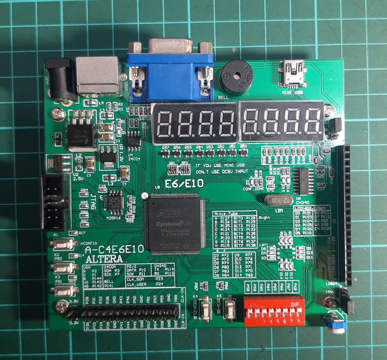
Altera Cyclone IV FPGA development board
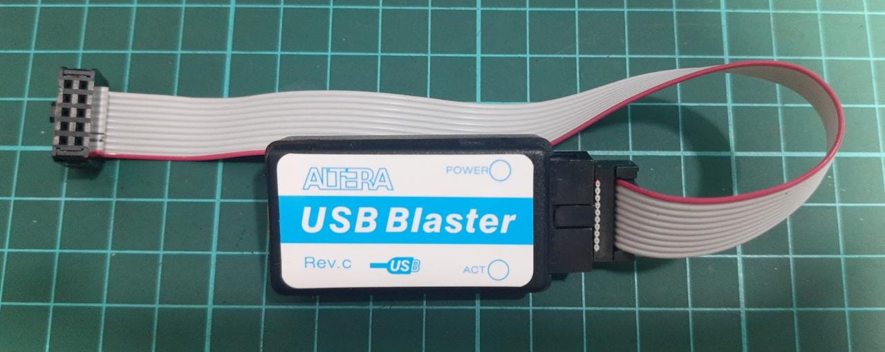
USB Blaster programmer connected to FPGA
Servo motor position control demonstration
DIP switch state machine controlling servo angles