PCB Mill: Precision CNC Drilling System
A Cartesian-type CNC drilling and milling machine designed for automated PCB perforation, circuit board fabrication, and precision miniature parts manufacturing with stepper motor control.
PCB Mill: Precision CNC Drilling System
Overview
A Cartesian-type CNC drilling and milling machine designed for automated PCB perforation, circuit board fabrication, and precision miniature parts manufacturing with stepper motor control.
Project Overview
The PCB Mill is a precision desktop CNC machine engineered for automated drilling, milling, and profiling of printed circuit boards and miniature components. Designed with a Cartesian coordinate system, this machine achieves high positional accuracy suitable for PCB manufacturing, micro-drilling, and precision prototyping applications.
Primary Applications
- PCB Drilling: Automated perforation of circuit boards with diameters from 0.5mm to 3.2mm
- Profile Cutting: Precision edge profiling and contouring of PCB edges
- Micro-milling: Small-scale subtractive manufacturing for precision parts
- Rapid Prototyping: Quick iteration for mechanical and electronic component fabrication
System Architecture
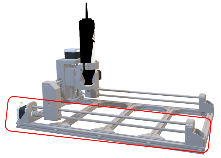
Mechanical Design
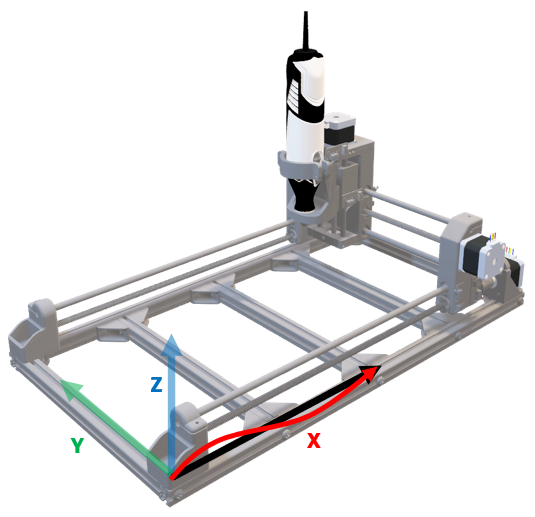
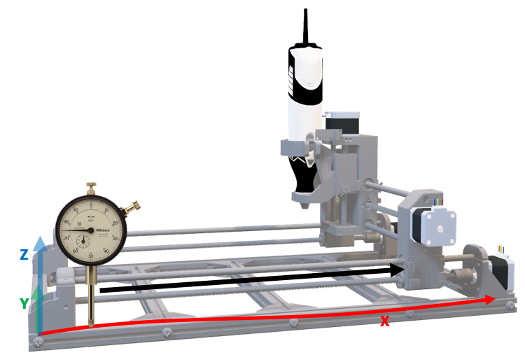
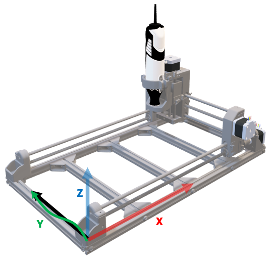
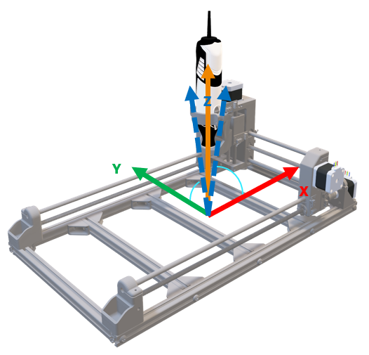
Coordinate System: Cartesian (X-Y-Z) configuration
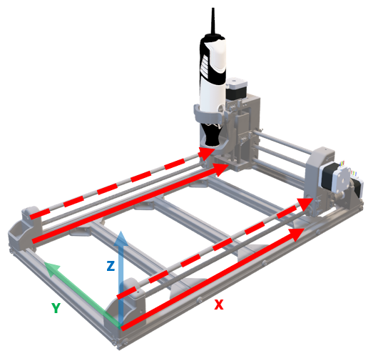
- X-Axis: Horizontal lateral movement (±150mm typical range)
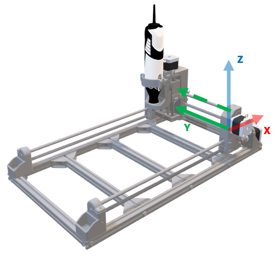
- Y-Axis: Horizontal depth movement (±100mm typical range)
- Z-Axis: Vertical spindle positioning (±50mm typical range)
Propulsion System
- Motor Type: Stepper Motors (NEMA 17/23 class)
- Drive Mechanism: GT2 timing belt with pulley reduction
- Precision: 0.1mm per microstep (16-microstep drivers)
- Control: GRBL firmware on Arduino Uno/Mega
Structural Components
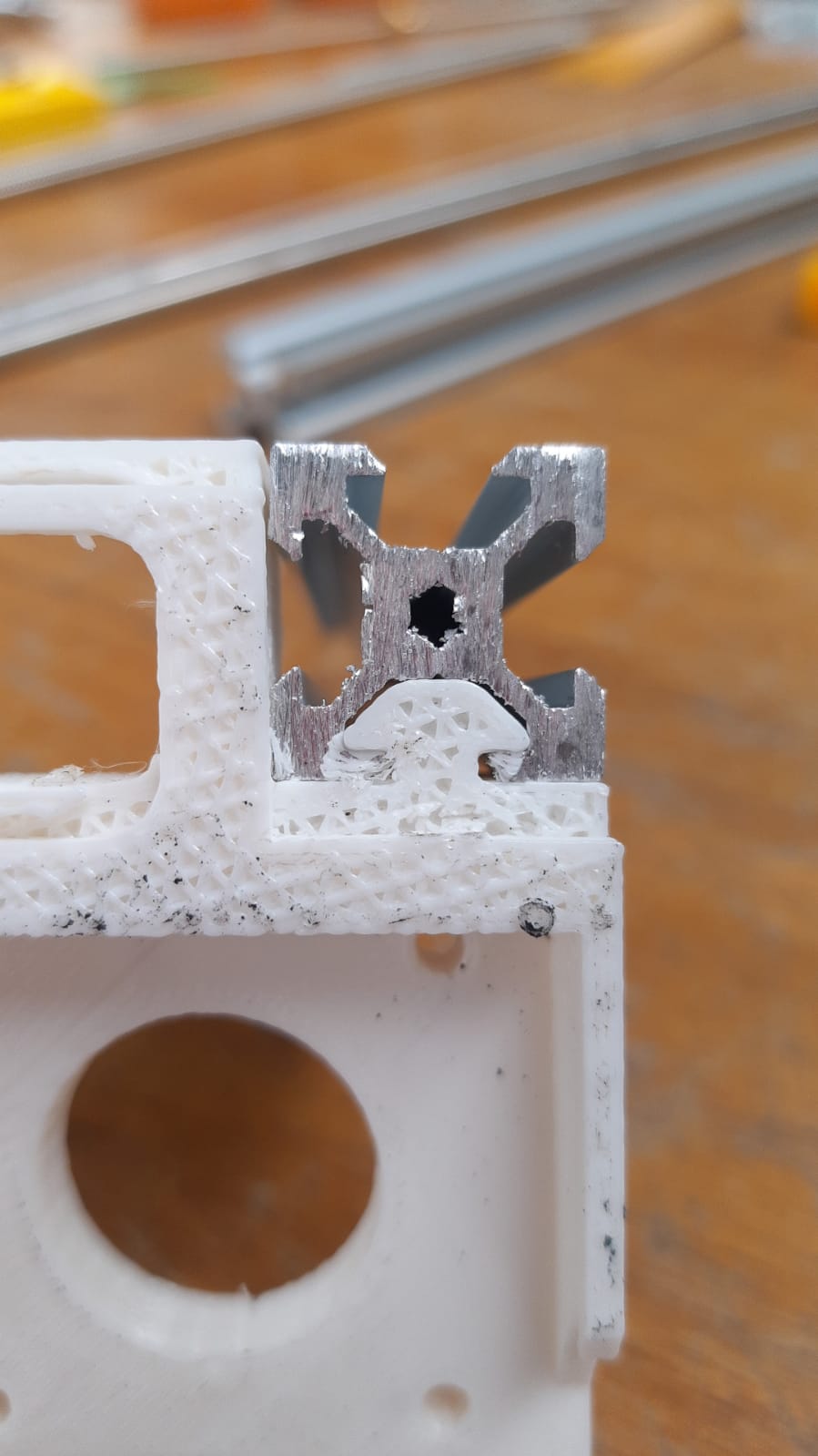
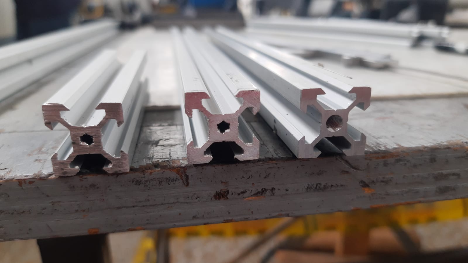
- Frame: Aluminum extrusion (20x20mm T-slot profile)
- Spindle Housing: Precision-machined aluminum or 3D printed composite
- Bearings: Linear ball bearings for low-friction motion
- Material Support: Vacuum hold-down or mechanical clamping fixture
Electronics & Control
Control Architecture
G-Code Input (CAM Software)
    ↓
Arduino Microcontroller (GRBL v1.1)
    ↓
CNC Shield (Stepper Driver Interface)
    ↓
NEMA 17/23 Stepper Motors
Electrical Specifications
- Supply Voltage: 12V DC (spindle), 5V DC (logic)
- Stepper Driver: A4988 or DRV8825 (3A current rating)
- Spindle Control: Variable speed PWM (0-24000 RPM typical)
- Limit Switches: Normally-open magnetic or mechanical
- Sensor Integration: Optional proximity sensors for tool change
Performance Characteristics
Accuracy & Repeatability
- Positional Accuracy: ±0.05mm (with proper calibration)
- Repeatability: ±0.02mm (multi-pass consistency)
- Surface Finish: Ra 1.6-3.2 μm (depending on tool and feed rate)
- Runout: < 0.1mm (spindle assembly specification)
Drilling Capabilities
- Hole Diameter Range: 0.5mm to 3.2mm (with standard bits)
- Drilling Speed: 18,000-24,000 RPM (typical spindle speed)
- Feed Rate: 10-50 mm/min (material dependent)
- Plunge Rate: 5-20 mm/min (preventing bit breakage)
- Throughput: ~30-50 holes per minute (PCB typical)
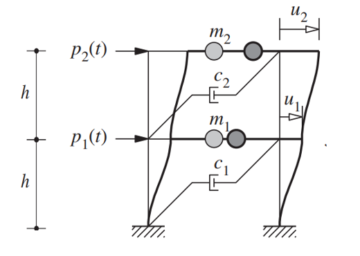
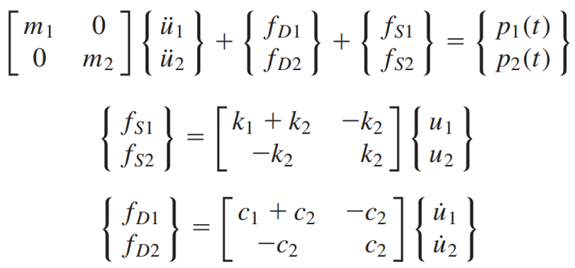
Vibration Analysis
Comprehensive vibration testing confirms acceptable levels across all operating frequencies:
- Excitation: Natural frequency ~45 Hz
- Damping Ratio: 0.08 (slightly underdamped for responsive control)
- Peak Acceleration: < 0.5g at full feed rate
Software & Workflow
CAM Processing Pipeline
- Design: Altium Designer, Eagle, or KiCad board layouts
- Conversion: PCB-to-GCode conversion (FlatCAM, pcb2gcode)
- Simulation: GRBL simulator for path verification
- Control: Grbl Controller or bCNC interface
- Execution: Real-time machine operation with feedback
Tool Library
| Tool Type | Diameter | Material | Max Speed |
|---|---|---|---|
| PCB Drill | 0.5-3.2mm | Carbide | 24,000 RPM |
| End Mill | 1.0-4.0mm | HSS/Carbide | 18,000 RPM |
| V-Bit | 60° included | Carbide | 12,000 RPM |
Fabrication Techniques
Subtractive Manufacturing Process
- Setup: Board fixturing and tool loading
- Initialization: Homing and coordinate reference
- Profiling: Outline and edge cutting (if required)
- Drilling: Hole perforation in sequence
- Inspection: Automated or visual verification
- Cleanup: Tool storage and material removal
Technical Documentation
For detailed specifications, manufacturing drawings, and assembly instructions, refer to the technical papers and design documentation included in this project.
Key References
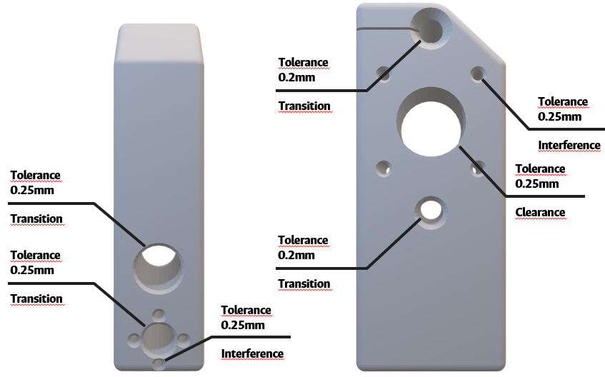
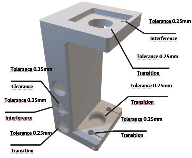
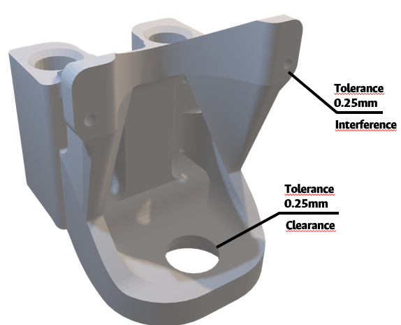
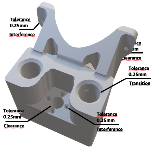
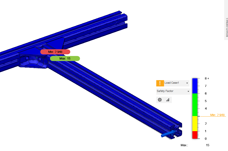
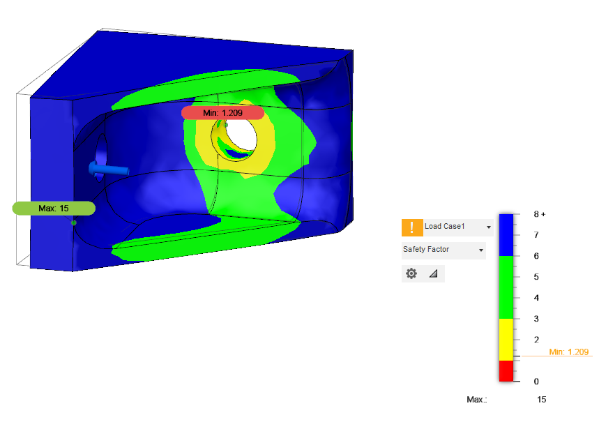
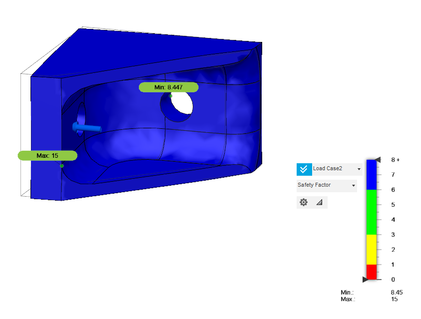
- GD&T Analysis: Comprehensive geometric and dimensional tolerance verification
- Vibration Characterization: Frequency response and damping analysis
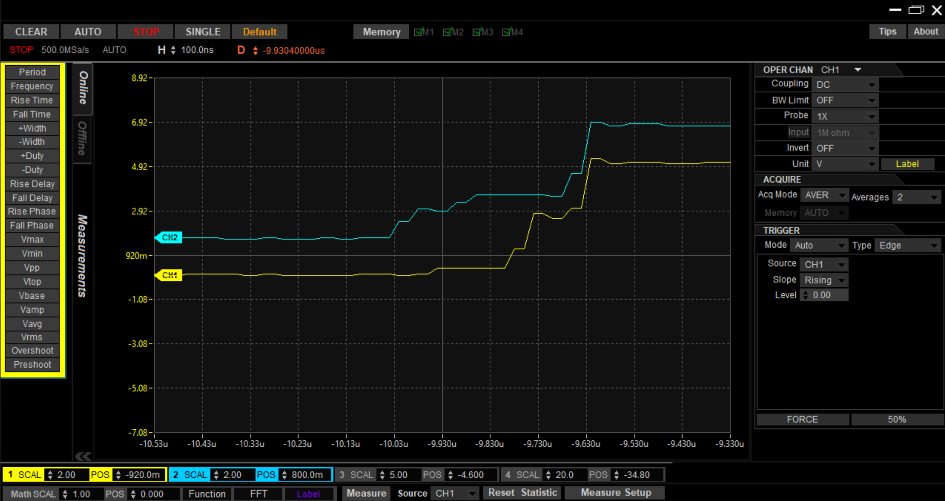
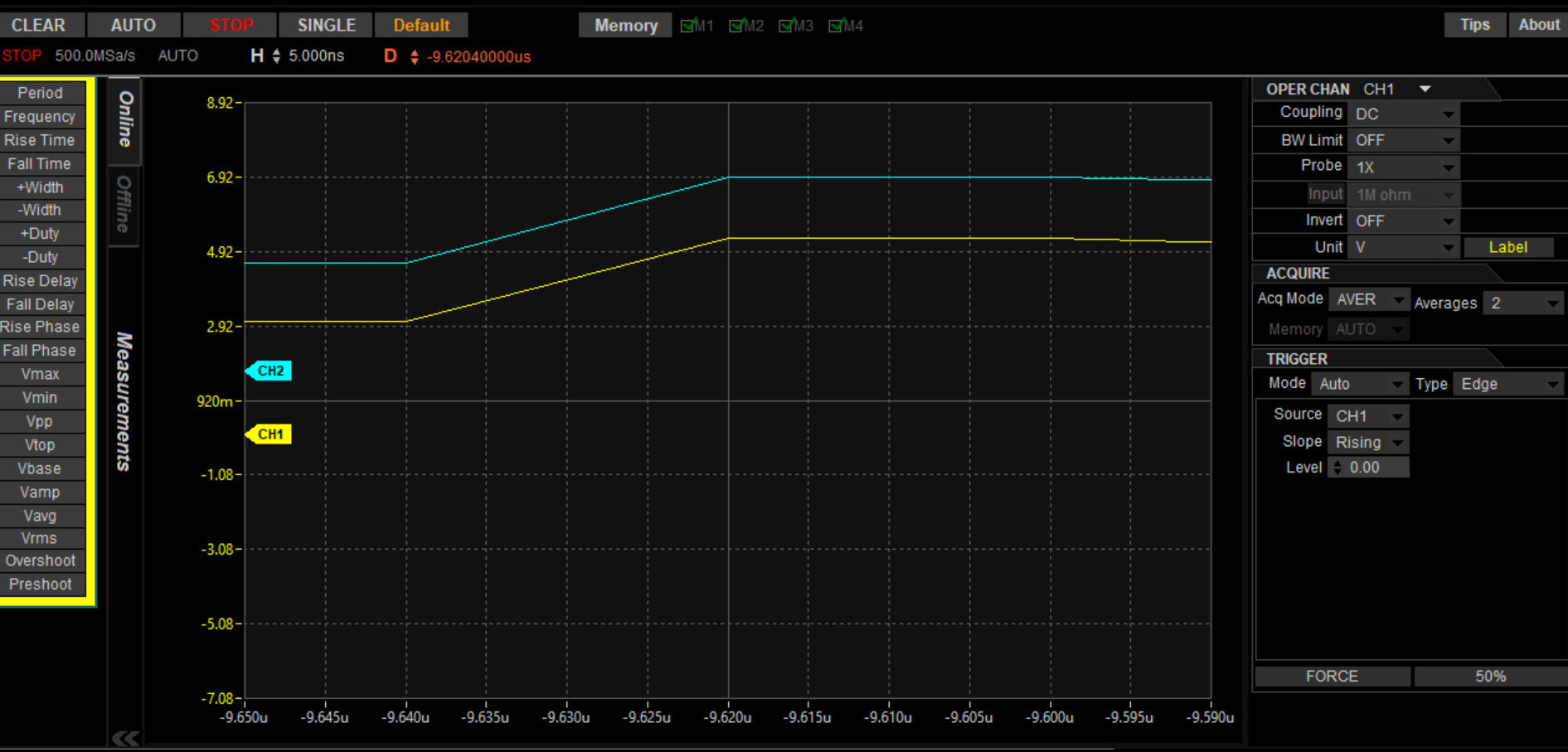
- Motor Synchronization: Dual-axis coordination for X-Y plane accuracy
- Design Evolution: Multiple design iterations (v1 through v34)
Design Considerations
Optimization Goals
- Accuracy: ±0.05mm positional tolerance
- Speed: Minimize cycle time for production runs
- Reliability: Consistent performance across extended operation
- Cost-Effectiveness: Minimize waste and tool wear
- Accessibility: User-friendly setup and operation
Manufacturing Constraints
- Bearing preload optimization for spindle runout
- Belt tension management for repeatable positioning
- Thermal stability of electronics and motors
- Chip management and cooling for high-speed operation
Future Enhancements
Potential improvements for next-generation iterations:
- Automatic Tool Changer: Reduce setup time for multi-tool operations
- Vacuum Table: Improve workpiece holding without mechanical clamps
- Real-time Monitoring: Accelerometer feedback for adaptive feed rate control
- Spindle Upgrade: Brushless DC or ER-collet spindle for improved runout
- Software Integration: CAM to machine communication for closed-loop verification
- Expanded Work Envelope: Larger X-Y-Z travel for bigger circuit boards
Specifications Summary
| Parameter | Specification |
|---|---|
| Machine Type | Cartesian CNC Router/Mill |
| Control System | GRBL + Arduino |
| Spindle Speed | 0-24,000 RPM |
| Working Area | 150 × 100 × 50 mm |
| Positioning Accuracy | ±0.05 mm |
| Tool Capacity | Single spindle (auto-changer optional) |
| Power Requirement | ~200W (typical operation) |
| Dimensions | ~600 × 500 × 400 mm |
| Weight | ~15-20 kg |
Resources
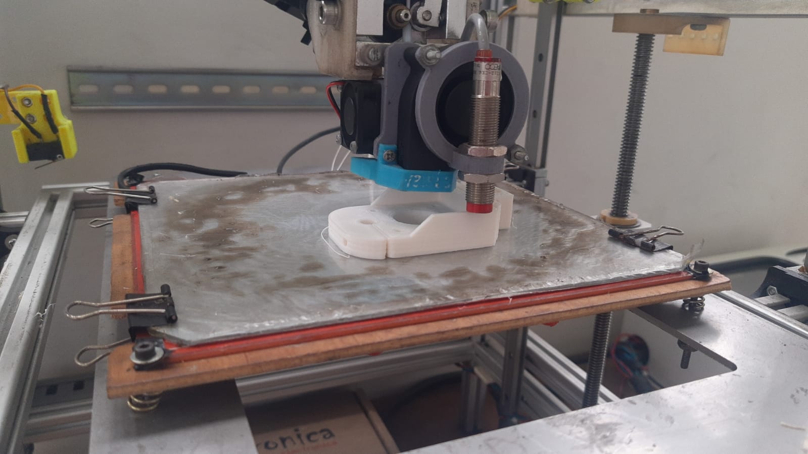
PCB Mill main operation demonstration
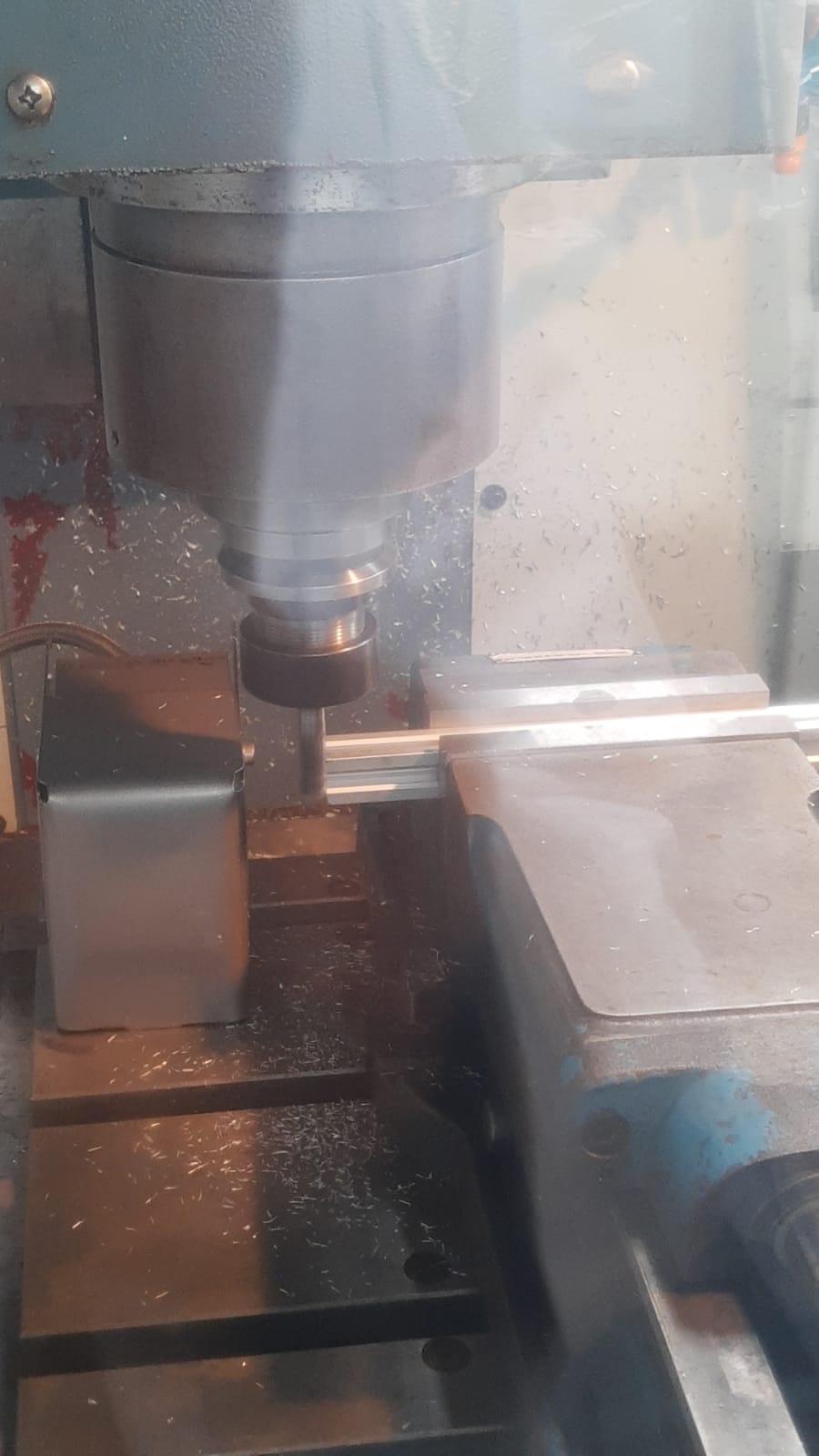
PCB Mill in operation - drilling process
PCB fixture and alignment system
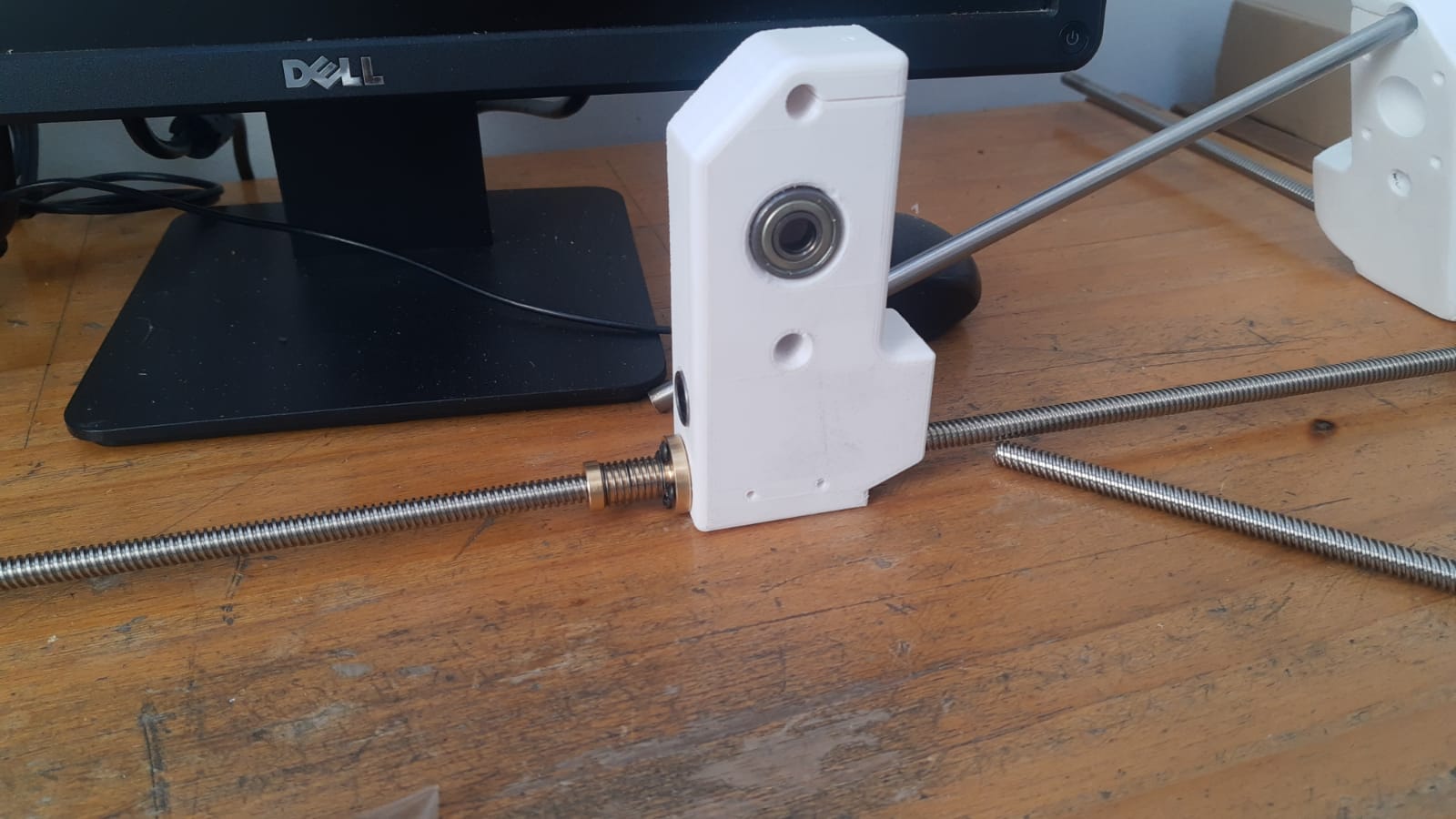
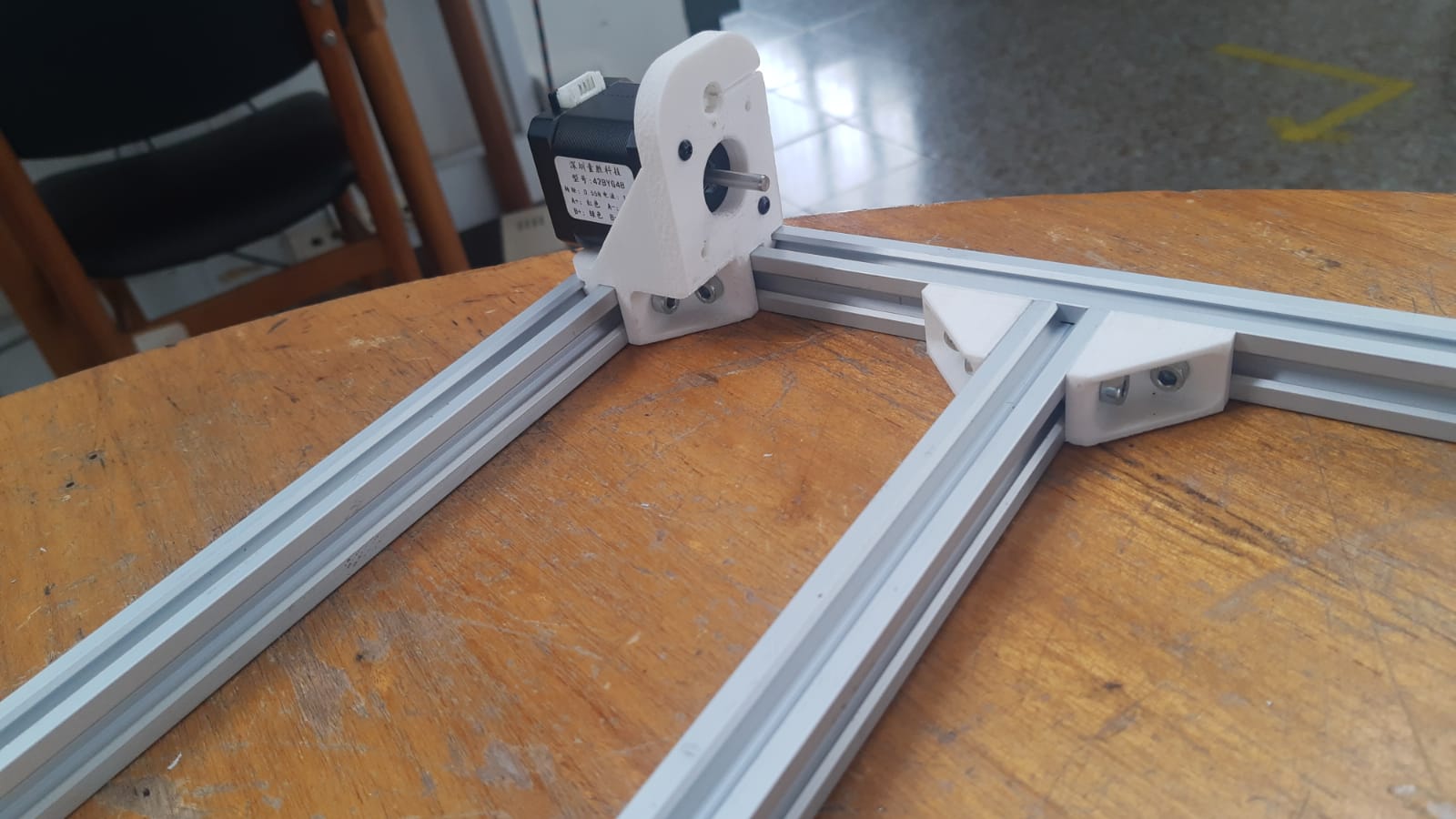
X-Y-Z axis assembly detail
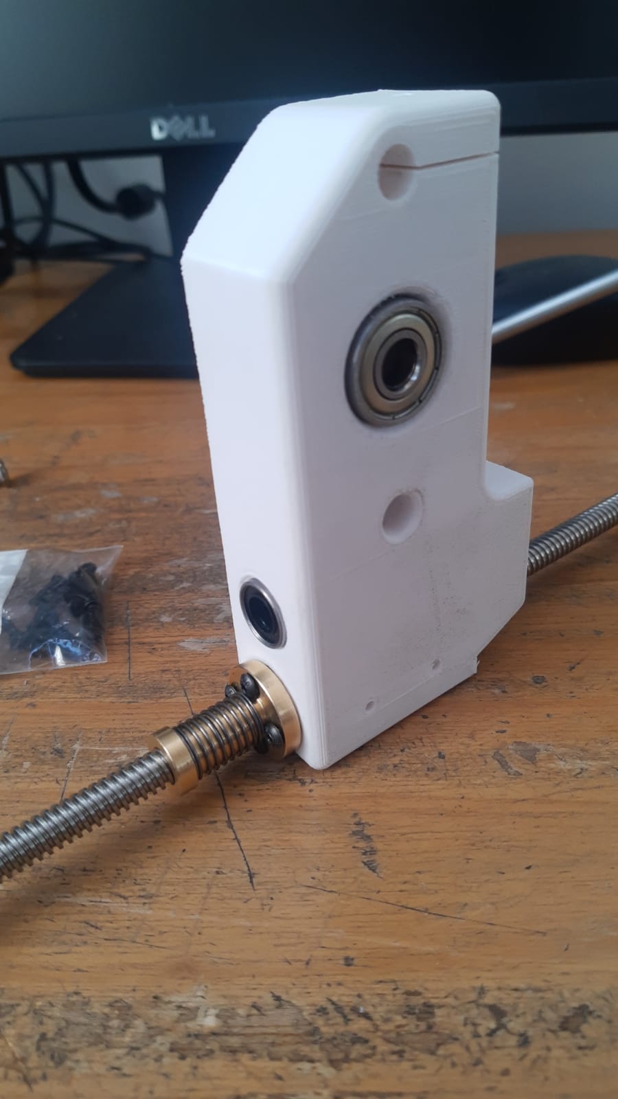
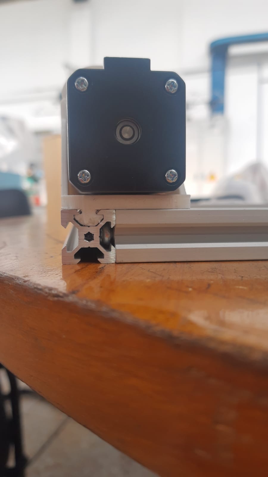
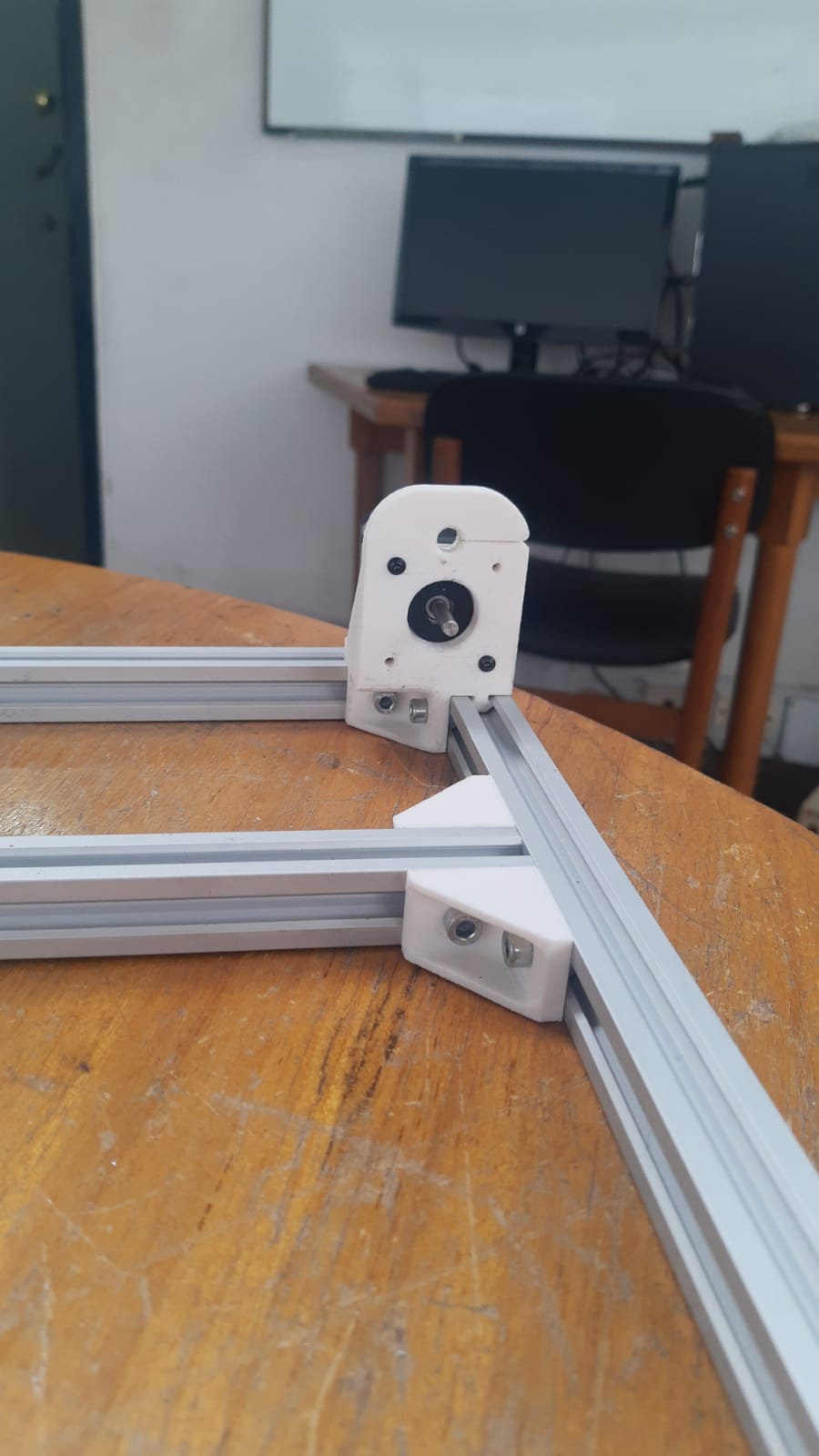
Stepper motor mounting configuration
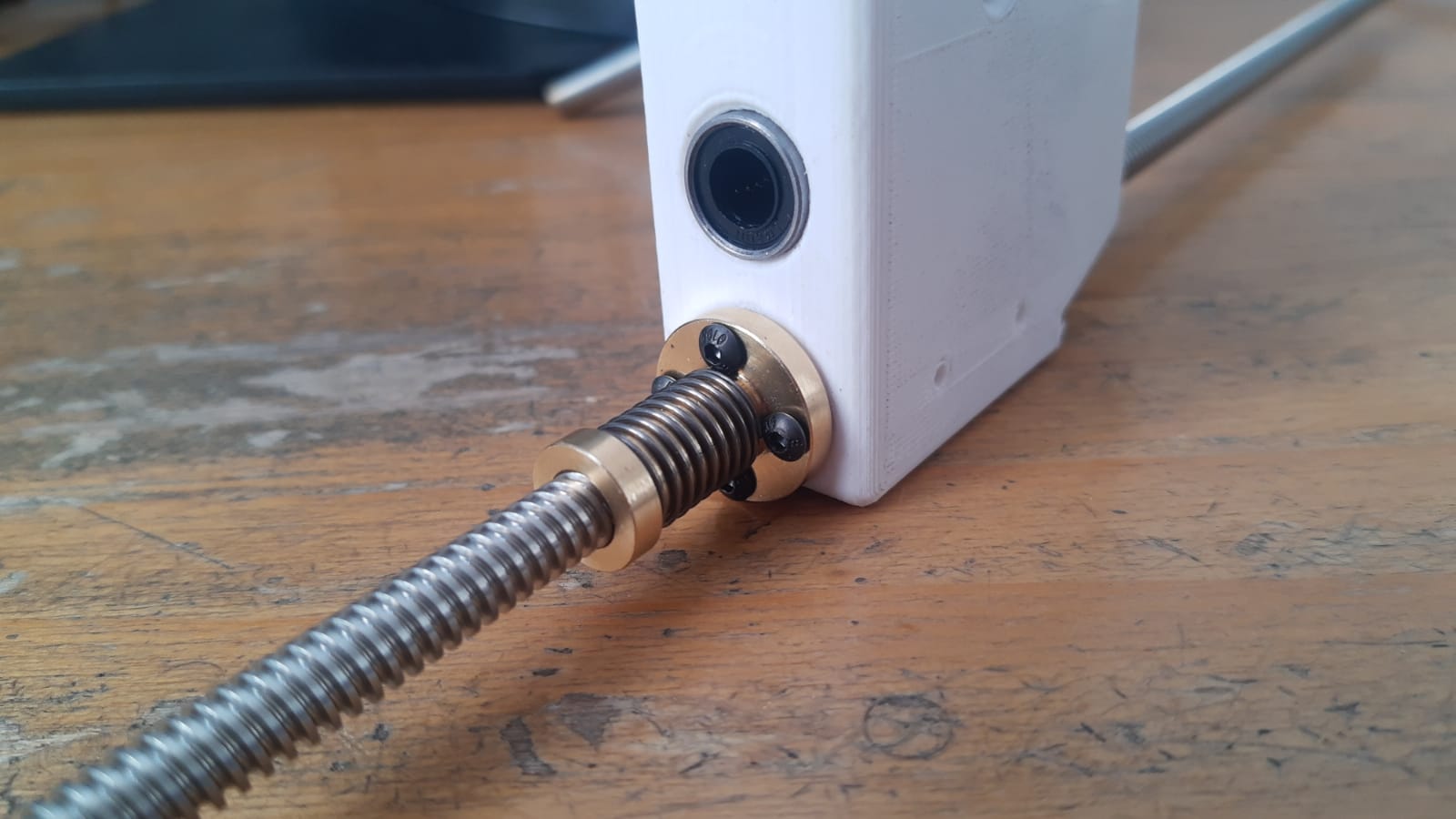
Belt drive and transmission system
Completed hole patterns on test PCB
Profile cutting demonstration
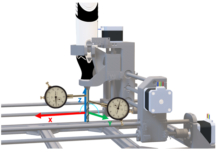
Machine calibration and alignment
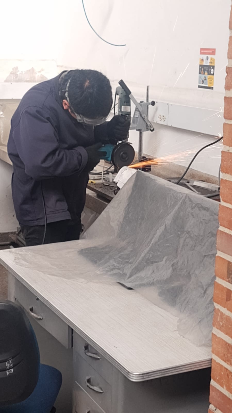
Cutting the Aluminium extrusions
Multi-layer PCB manufacturing results
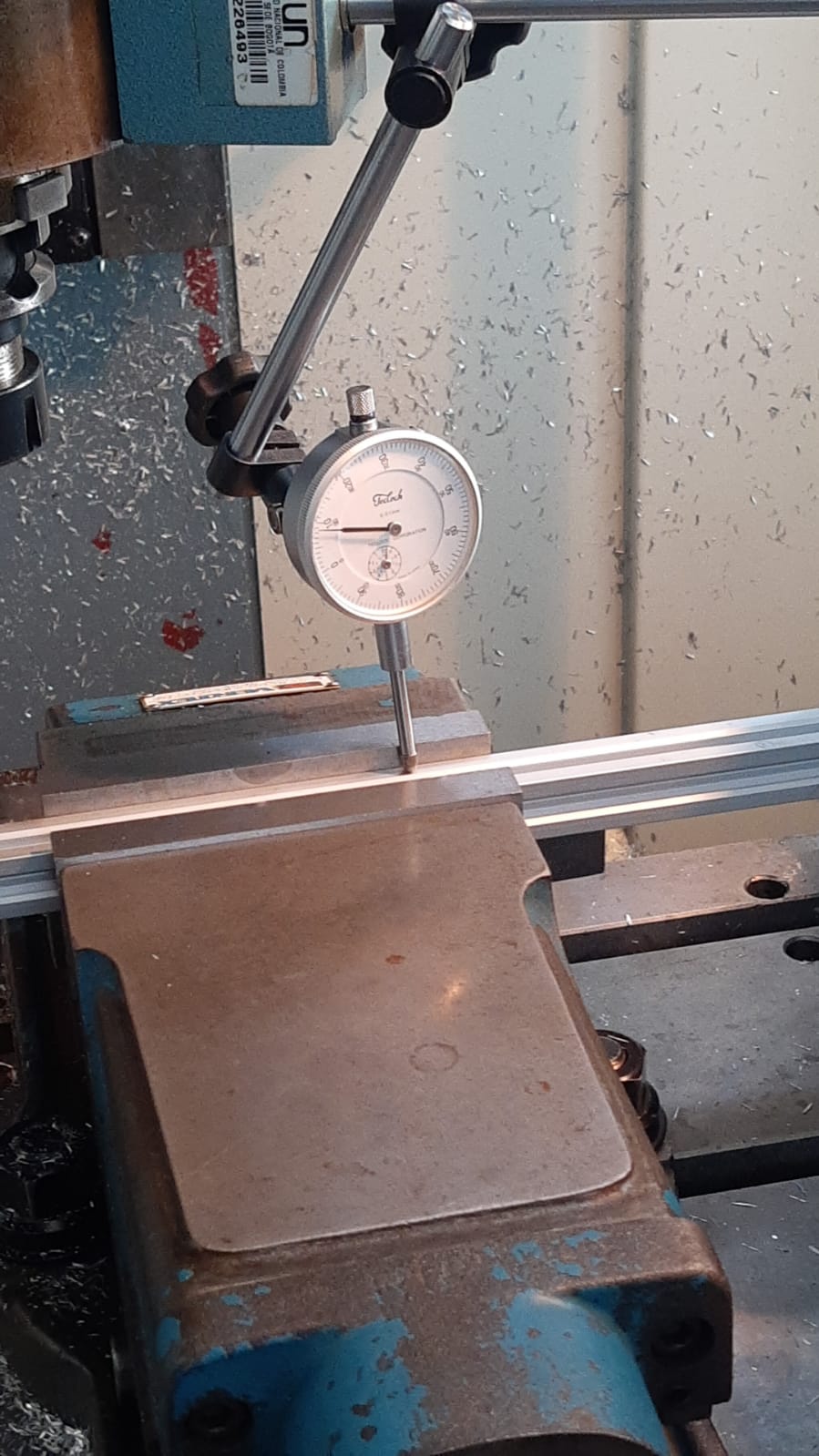
Precision tolerance verification
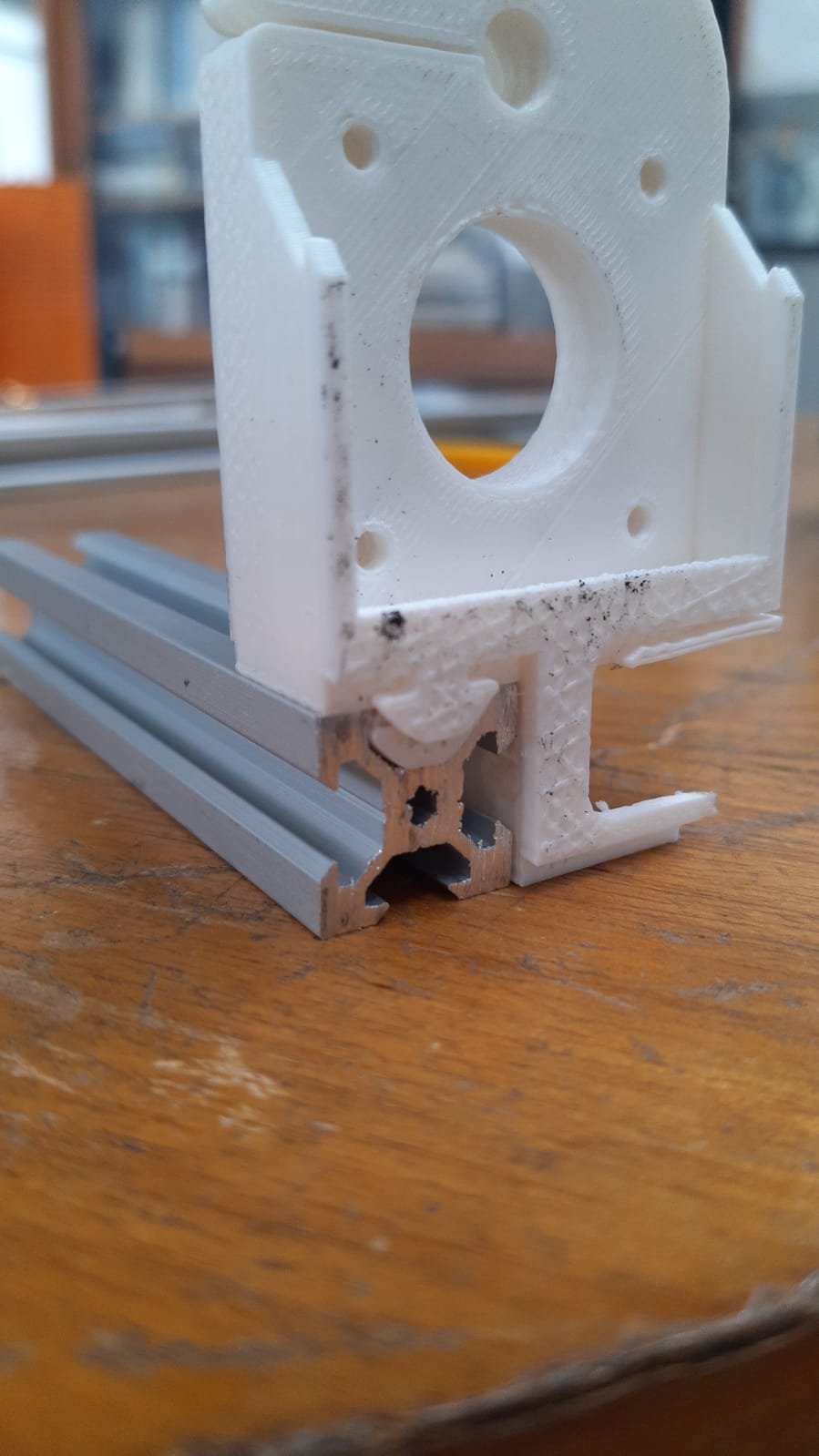
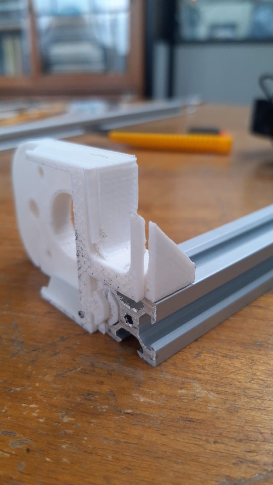
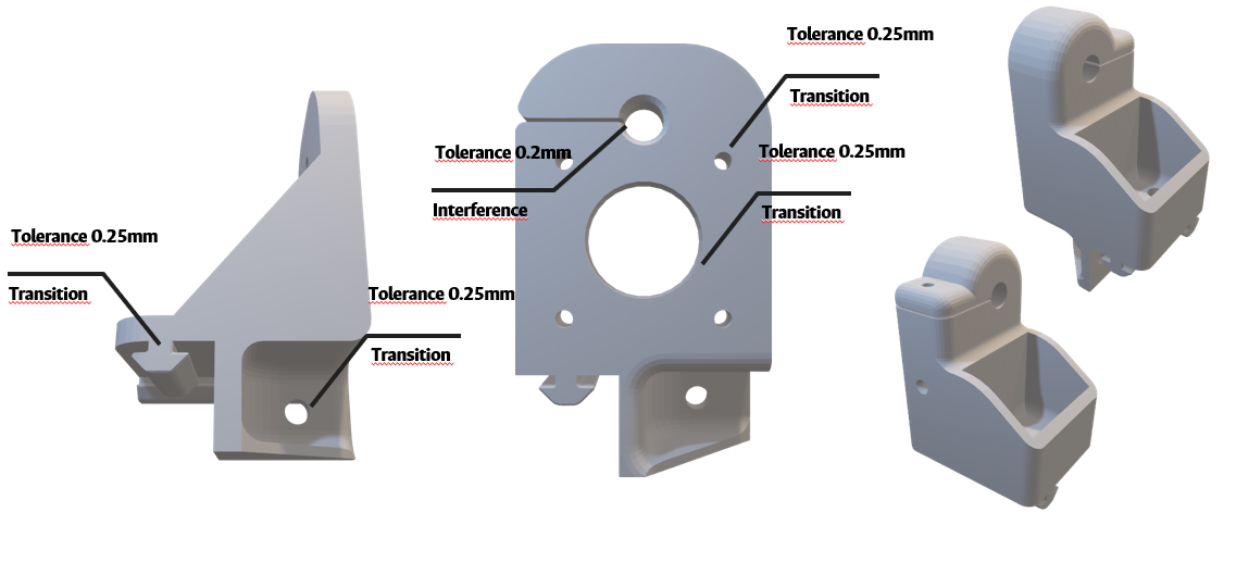
Precision of tolerance in additive manufacturing
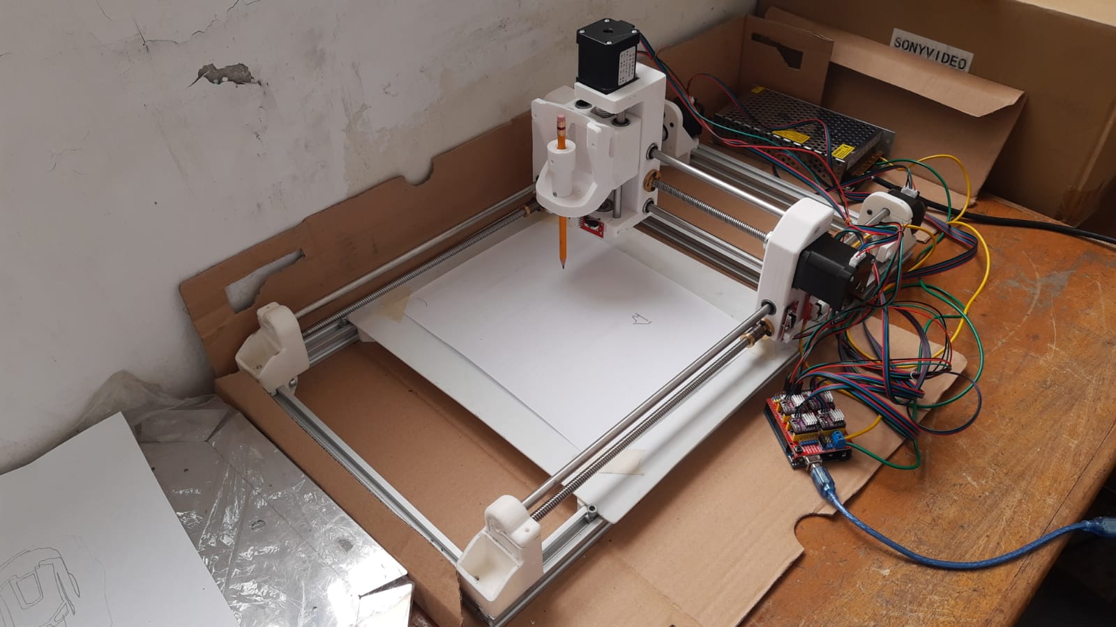
Full machine assembly side view
Working envelope and operational space
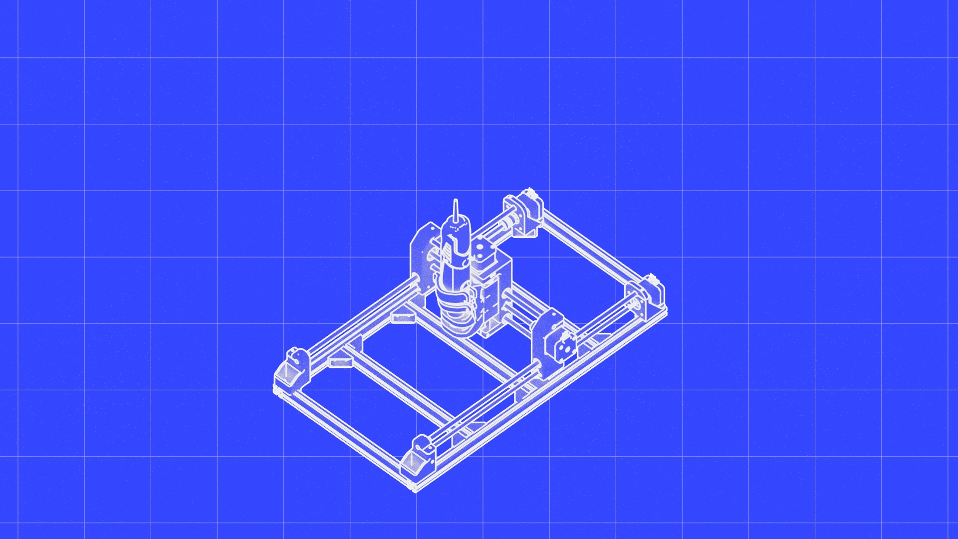
STL model visualization and preview
Machine operation animation
Profile cutting edge quality
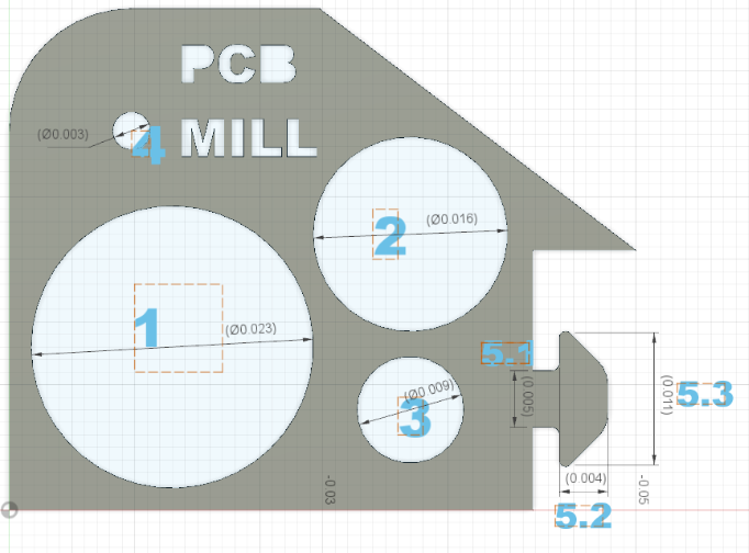
Geometric and positional tolerance specifications
GD&T Analysis - Runout Control
GD&T Analysis - Flatness Definition
GD&T Analysis - Perpendicularity
GD&T Analysis - Position Control
GD&T Analysis - Composite Tolerance
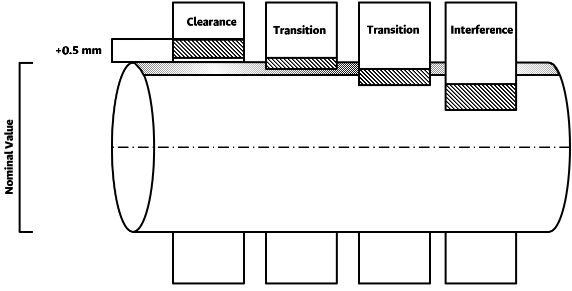
Clearance Value Calculations
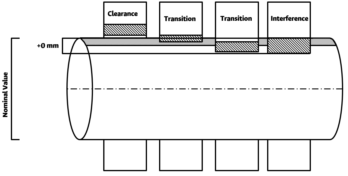
Interference Analysis
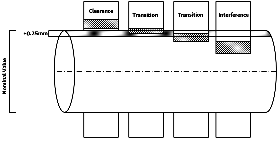
Transition Fit Verification

GD&T Type 1 - Feature Analysis
GD&T Type 2 - Datum Establishment
GD&T Type 3 - Control Frame
GD&T Type 4 - Modifier Application
GD&T Type 5 - Measurement Strategy

GD&T Type 6 - Report Generation
GD&T Type 7 - Fixture Design

GD&T Type 8 - Tolerance Stacking

GD&T Type 9 - CMM Programming
GD&T Type 10 - Statistical Analysis
GD&T Type 11 - Advanced Verification
Angle Bracket Design 1
Angle Bracket Support Structure
Reinforced Bracket Support
Phase Offset in Z-Axis Motion
Top-view Phase Relationship
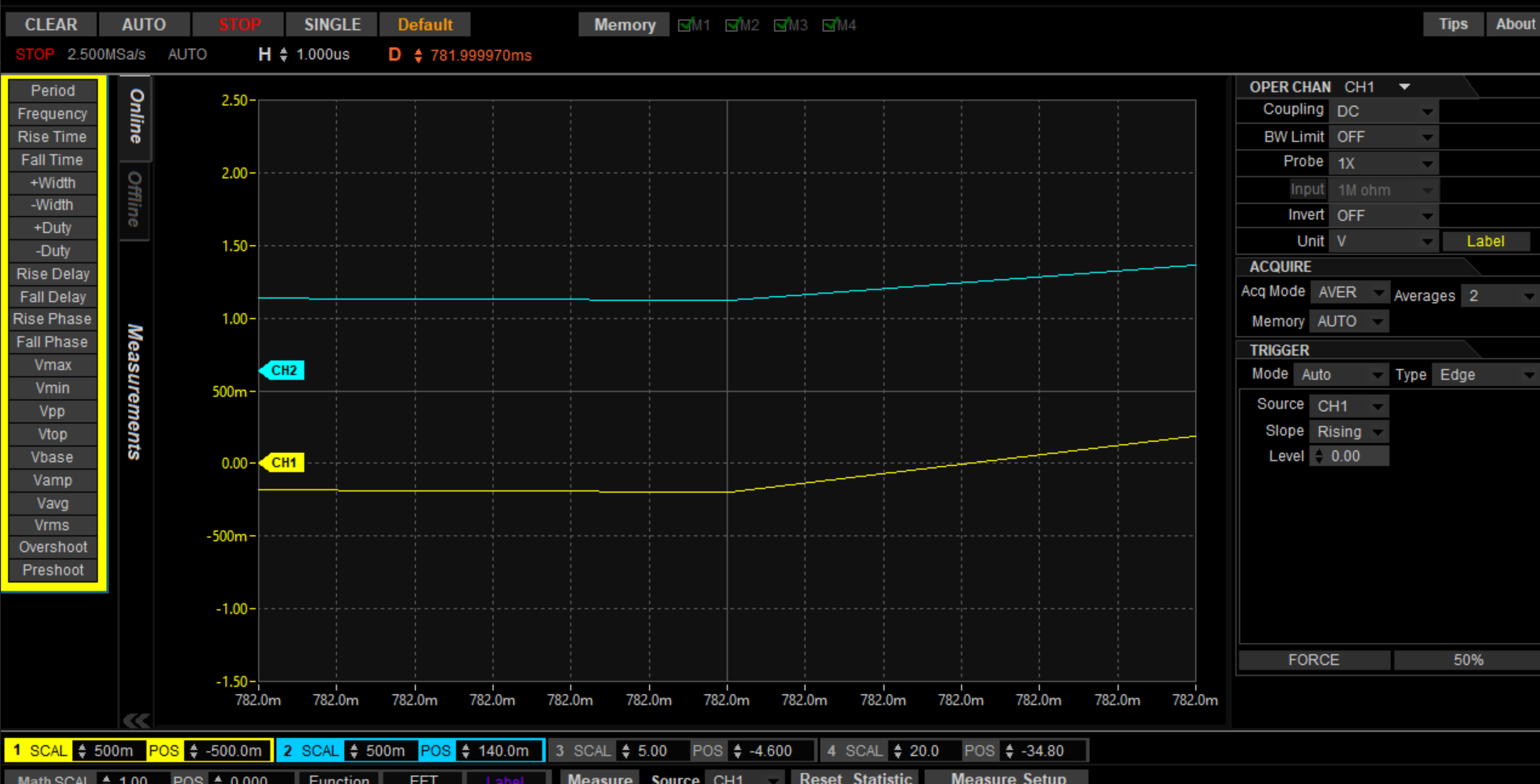
Fine Motor Synchronization Plot
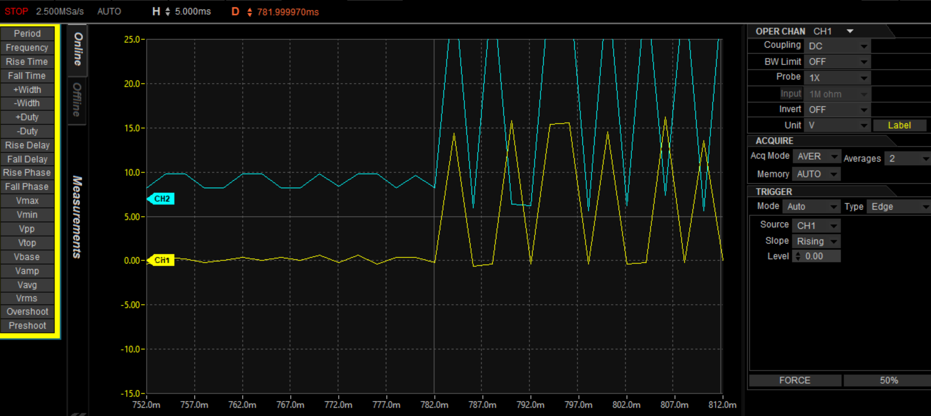
Horizontal Motor Sync Data
Vibration Analysis - Frequency Domain
Vibration Spectrum - X Axis
Vibration Spectrum - Z Axis
Cumulative Vibration Energy