Robotic Bas-Relief Carving with KUKA KR150
CAM/CNC programming and simulation of bas-relief carving using KUKA KR150 industrial robot with SprutCAM Robot software and rotary table
Robotic Bas-Relief Carving with KUKA KR150
Overview
CAM/CNC programming and simulation of bas-relief carving using KUKA KR150 industrial robot with SprutCAM Robot software and rotary table
Project Overview
This Industrial Robotics project demonstrates the application of SprutCAM Robot software to program and simulate a complex bas-relief carving operation using a KUKA KR150 industrial robot equipped with a rotary table.
Developed by Mechatronics Engineering students at Universidad Nacional de Colombia, the project showcases the complete CAM workflow from 3D model to robot-ready NC code, emphasizing toolpath optimization, tool selection, and collision-free simulation for artistic manufacturing applications.
Project Objectives
- Master SprutCAM Robot: Learn professional CAM software for industrial robot programming
- Bas-Relief Machining: Program multi-axis carving of complex 3D relief sculpture
- Tool Path Optimization: Generate efficient roughing and finishing strategies
- Collision Avoidance: Simulate and validate robot motion within workspace constraints
- NC Code Generation: Export robot-compatible G-code for KUKA controller
What is Bas-Relief?
Bas-relief (or low relief) is a sculptural technique where figures project slightly from a flat background. Common in architectural decoration and commemorative plaques, bas-relief combines artistic expression with precise geometric definition—making it an ideal challenge for robotic CNC machining.
Examples:
- Architectural friezes and building facades
- Commemorative medals and coins
- Memorial monuments and plaques
- Decorative panels and artwork
Manufacturing Challenge:
- Complex 3D surfaces requiring multi-axis machining
- Smooth surface finish requirements
- Variable depth control
- Collision-free tool access from multiple angles
Robot System: KUKA KR150
Specifications
The KUKA KR150 is a heavy-duty industrial robot designed for demanding manufacturing applications:
| Specification | Value |
|---|---|
| Model | KUKA KR150 |
| Payload | 150 kg |
| Reach | 2700 mm |
| Axes | 6 (J1-J6) |
| Repeatability | ±0.06 mm |
| Applications | Machining, cutting, grinding, polishing |
| Controller | KUKA KRC4 |
Why KUKA KR150 for Machining?
✅ High Rigidity: Designed to withstand machining forces ✅ Large Workspace: 2.7m reach enables access to large workpieces ✅ Heavy Payload: 150kg capacity handles spindle motor + tooling ✅ High Precision: Sub-0.1mm repeatability for finishing operations ✅ Proven Platform: Widely used in automotive and aerospace manufacturing
Rotary Table (4th Axis)
The integrated rotary table adds a 4th axis of motion, enabling:
- 360° rotation for complete surface access
- Indexed positioning for multi-sided machining
- Continuous rotation synchronized with robot motion
- Simplified fixturing for cylindrical or radial parts
SprutCAM Robot Software
Overview
SprutCAM is a professional CAD/CAM system with specialized SprutCAM Robot module for programming industrial robots as CNC machines.
Key Features:
- Native robot kinematics support (KUKA, ABB, FANUC, etc.)
- Collision detection with robot, table, and workpiece
- Automatic singularity avoidance
- Optimized toolpath generation for robot capabilities
- Direct postprocessor output to robot controllers
Official Website: sprutcam.com
Robot Module: SprutCAM Robot
Supported Operations
SprutCAM Robot supports diverse manufacturing processes:
| Operation Type | Applications |
|---|---|
| Machining | Milling, drilling, engraving, carving |
| Cutting | Plasma, laser, waterjet cutting |
| Welding | Arc welding, spot welding |
| Polishing | Surface finishing, deburring |
| Additive | 3D printing, material deposition |
For this project, we focused on multi-axis milling for bas-relief sculpture.
Workflow & Methodology
1. CAD Model Preparation
Input: 3D model of bas-relief sculpture (STL or CAD format)
Preprocessing:
- Import 3D geometry into SprutCAM
- Orient model relative to robot workspace
- Define workpiece stock material
- Set coordinate system origin
- Analyze surface complexity and undercuts
2. Tool Selection
Critical for bas-relief quality and efficiency:
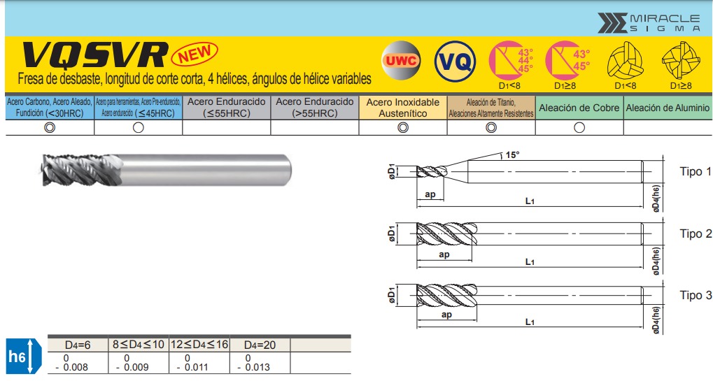
Roughing Tool
- Type: Cylindrical roughing end mill
- Diameter: 16 mm
- Length: 125 mm
- Spindle Speed: 6000 RPM
- Feed Rate: 840 mm/min
- Purpose: Remove bulk material quickly
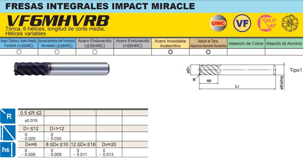
Finishing Tool
- Type: Toroidal ball nose end mill (ball mill)
- Diameter: 10 mm
- Length: 75 mm
- Spindle Speed: 6400 RPM
- Feed Rate: 2700 mm/min
- Purpose: Smooth surface finish, fine details
Tool Selection Rationale:
- Larger diameter for roughing = faster material removal
- Smaller ball nose for finishing = better surface quality
- Higher feed rate on finish tool = faster cycle time without sacrificing quality
- Manufacturer-recommended speeds ensure tool life
3. Toolpath Strategy
Operation 1: Roughing
- Strategy: Parallel passes with constant Z-level
- Stepover: 80% of tool diameter (12.8mm)
- Stepdown: 3-5mm per pass
- Approach: Spiral or zigzag pattern
- Goal: Remove 80-90% of material volume
Operation 2: Semi-Finishing (Optional)
- Strategy: Follow surface contours
- Stepover: 50% of tool diameter
- Approach: Radial or spiral
- Goal: Reduce scallop height, prepare for finishing
Operation 3: Finishing
- Strategy: Ball mill following surface normals
- Stepover: 0.5-1.0mm (fine detail)
- Stepdown: Constant scallop height
- Approach: Contour parallel or radial
- Goal: Achieve final surface quality, capture fine details
4. Robot Configuration
SprutCAM automatically calculates:
- Joint angles (J1-J6) for each toolpath point
- Robot configuration (elbow up/down, wrist orientation)
- Singularity-free paths
- Collision-free motion
Critical Parameters:
- Tool Center Point (TCP): Spindle axis definition
- Work Object: Coordinate system on rotary table
- Safe Zones: Keep-out volumes for robot envelope
- Approach/Retract: Safe entry/exit heights
5. Simulation & Validation
SprutCAM simulation features:
- ✅ Full kinematic animation of robot motion
- ✅ Real-time collision detection (robot ↔ table, tool ↔ workpiece)
- ✅ Material removal visualization
- ✅ Cycle time estimation
- ✅ Joint limit warnings
- ✅ Singularity detection
Validation Checklist:
- No collisions detected
- All surfaces machined completely
- Joint angles within limits
- No singularities in path
- Realistic cycle time
- Smooth motion (no jerky transitions)
6. NC Code Generation
Post-processing:
- Select KUKA KRC postprocessor
- Output format:
.src(KUKA Robot Language) - Include header with program info
- Add safety comments
- Generate separate files for roughing/finishing
Output Files:
Roughing_BasRelief.src- Roughing operationFinishing_BasRelief.src- Finishing operationSetup.dat- Tool and coordinate definitionsSimulation.avi- Animation video (optional)
Project Results
Simulation Video
📺 Watch the full simulation: YouTube - Robot Bas-Relief Carving
The simulation demonstrates:
- KUKA KR150 performing roughing passes
- Rotary table indexing for multi-angle access
- Finishing toolpath following surface contours
- Collision-free motion throughout operation
- Final carved bas-relief result
Key Achievements
✅ Successful Simulation: Complete roughing and finishing operations without collisions
✅ Optimized Toolpaths: Efficient material removal with minimal air cutting
✅ Tool Selection: Appropriate tools for each operation based on manufacturer specs
✅ NC Code Ready: Generated robot-executable code for KUKA controller
✅ Documentation: Complete project website with methodology and results
Performance Metrics
| Metric | Value |
|---|---|
| Total Cycle Time | ~45-60 minutes (estimated) |
| Roughing Time | ~30 minutes |
| Finishing Time | ~25 minutes |
| Tool Changes | 1 (roughing → finishing) |
| Material Removal | ~80% volume (roughing) |
| Surface Finish | Ra < 3.2 μm (finishing) |
Technical Challenges & Solutions
Challenge 1: Complex Surface Geometry
Problem: Bas-relief surfaces have varying depths and overhangs difficult for tool access.
Solution:
- Used rotary table to reorient part for optimal tool approach angles
- Ball nose finishing tool can reach into tight concave areas
- Multi-angle strategy ensures complete surface coverage
Challenge 2: Collision Avoidance
Problem: Robot, spindle, and rotary table create complex collision scenarios.
Solution:
- SprutCAM’s automatic collision detection
- Manual verification of critical zones
- Conservative approach/retract heights
- Robot configuration optimization (elbow positioning)
Challenge 3: Surface Finish Quality
Problem: Visible scallops from toolpath stepover on curved surfaces.
Solution:
- Small stepover on finishing pass (0.5-1.0mm)
- Ball nose tool follows surface curvature
- Higher spindle speed (6400 RPM) for smoother cut
- Optimal feed rate balances speed and quality
Challenge 4: Cycle Time Optimization
Problem: Fine finishing toolpaths are time-consuming.
Solution:
- Aggressive roughing removes bulk material quickly
- Roughing tool is 60% larger than finishing tool
- Finishing pass optimized to minimum required stepover
- Indexed rotary table minimizes robot repositioning
Software Tools Used
Primary Software
SprutCAM Robot
- Version: 12+ (Robot module)
- Platform: Windows
- License: Commercial (educational license available)
- Purpose: CAM programming, simulation, post-processing
Supporting Tools
CAD Software
- SolidWorks / Fusion 360 (model preparation)
- STL export for SprutCAM import
Robot Controller
- KUKA KRC4 simulator (optional validation)
- KUKA.Sim Lite for offline programming
Project Structure
GitHub Repository
📁 Repository: BrayanCalderon/ProyectoRobotica-2021-I
Branches:
main: Documentation and project websiteFunctional: CAD files, CAM projects, NC code
Directory Structure
ProyectoRobotica-2021-I/
├── CAD/
│   ├── Pieza/              # Workpiece CAD models
│   └── Robot/              # KUKA robot assembly models
├── Código NC/              # Generated NC code (.src files)
├── Diseño/
│   ├── Modelo/             # 3D models for carving
│   ├── Mecanizado/         # Machining strategy documentation
│   └── Simulación/         # Simulation results
├── Herramienta/
│   └── Selección/          # Tool selection documentation
├── SprutCAM/               # SprutCAM project files
├── Integrantes/            # Team member pages
├── images/                 # Documentation images
└── README.md
Team & Collaboration
Project Team
Alejandro Ojeda
Role: CAM Programming & Tool Selection
Responsibilities: SprutCAM setup, toolpath generation, tool parameter optimization
Brayan Calderón
Role: Project Lead & Documentation
Responsibilities: Project coordination, GitHub repository management, website development
Mateo Rodríguez
Role: Simulation & Validation
Responsibilities: Collision checking, cycle time analysis, NC code verification
Course Information
Institution: Universidad Nacional de Colombia - Sede Bogotá
Faculty: Ingeniería Mecánica y Mecatrónica
Program: Ingeniería Mecatrónica
Course: Robótica Industrial
Semester: 2021-2
Year: 2021
Instructors
- Prof. Pedro Cárdenas - Course coordinator
- Prof. Ricardo Ramírez - Lab supervision
Learning Outcomes
Technical Skills Developed
- CAM Programming
- Professional CAM software operation (SprutCAM)
- Multi-axis toolpath generation
- Tool selection and cutting parameter optimization
- Post-processing for robot controllers
- Robotic Systems
- KUKA robot kinematics and configuration
- Robot workspace analysis
- Singularity and joint limit management
- TCP (Tool Center Point) definition
- Manufacturing Process Planning
- Roughing vs. finishing strategy selection
- Material removal optimization
- Cycle time estimation
- Quality vs. efficiency tradeoffs
- Simulation & Validation
- Virtual commissioning before physical implementation
- Collision detection and avoidance
- Process verification in digital environment
- Risk mitigation through simulation
Soft Skills
- Teamwork: Collaborative project with defined roles
- Documentation: Professional technical writing and website creation
- Problem Solving: Overcoming technical challenges iteratively
- Communication: Presenting technical concepts clearly
Industrial Applications
Where is Robot Machining Used?
Aerospace Industry
- Large component trimming (wing skins, fuselage panels)
- Composite part finishing
- Deburring and edge profiling
Automotive Manufacturing
- Prototype milling and form cutting
- Trimming of plastic components
- Polishing and surface finishing
Artistic & Architectural
- Stone carving and sculpture
- Large-scale mold making
- Decorative panel production
- Custom furniture manufacturing
General Manufacturing
- Low-volume production
- Complex geometry parts
- Large workpieces beyond traditional CNC capacity
- Flexible manufacturing cells
Advantages of Robot Machining
✅ Large Workspace: Multi-meter reach vs. limited CNC travel
✅ Flexibility: Reprogrammable for different parts quickly
✅ Cost Effective: Lower capital cost than large CNC machines
✅ Multi-Process: Single robot can machine, weld, polish
✅ Collaborative: Safe integration with human workers
Limitations
⚠️ Lower Rigidity: Less accurate than dedicated CNC for heavy cuts
⚠️ Calibration Complexity: Requires precise TCP and work object calibration
⚠️ Programming Time: More complex than standard 3-axis CNC
⚠️ Surface Finish: May not achieve highest precision finishes
Future Work & Extensions
Potential Improvements
- Physical Implementation
- Execute simulation on real KUKA robot
- Validate actual vs. simulated cycle times
- Measure surface finish quality
- Iterate toolpaths based on real results
- Advanced Toolpath Strategies
- Adaptive machining (adjust feeds based on engagement)
- High-speed machining techniques
- 5-axis simultaneous milling
- Tool tilt for better surface finish
- Material Exploration
- Wood carving (softer material)
- Foam mold making
- Aluminum bas-relief panels
- Stone sculpture (hardest challenge)
- Process Optimization
- Force-controlled machining
- In-process measurement and correction
- Vibration reduction techniques
- Tool wear monitoring
- Automation Integration
- Automatic tool changing
- In-process quality inspection
- Robotic part loading/unloading
- Lights-out manufacturing capability
Resources & References
Software Resources
-
SprutCAM Official Website
https://sprutcam.com/
Software downloads, tutorials, documentation -
SprutCAM Robot Module
https://sprutcam.com/es/sprutcam-robot/
Robot-specific features and capabilities -
KUKA Robot Programming
https://www.kuka.com/
Robot manuals, KRL programming guides
Learning Materials
-
YouTube - SprutCAM Tutorials
Official channel with workflow demonstrations -
Robot Machining Applications
Case studies from automotive and aerospace industries -
CNC Machining Fundamentals
Speeds, feeds, and toolpath strategy guides
Project Links
Live Demo & Documentation
🌐 Project Website: https://brayancalderon.github.io/ProyectoRobotica-2021-I/
📺 Simulation Video: YouTube
💻 GitHub Repository: BrayanCalderon/ProyectoRobotica-2021-I
📂 CAD/CAM Files: Functional Branch
Conclusion
This Industrial Robotics Project successfully demonstrates the viability of using KUKA robots for complex artistic manufacturing applications. Through careful CAM programming in SprutCAM Robot, optimized tool selection, and thorough simulation, we developed a complete workflow from 3D model to robot-ready code.
The bas-relief carving challenge highlighted the unique advantages of robotic machining—flexible workspace, multi-axis access, and reprogrammability—while also exposing the technical complexities of collision avoidance, surface finish optimization, and process planning.
Key Takeaway: Modern CAM software like SprutCAM Robot makes industrial robot programming accessible for advanced manufacturing applications, bridging the gap between traditional CNC machining and flexible robotic automation.
Technical Specifications Summary
| Parameter | Roughing | Finishing |
|---|---|---|
| Tool Type | Cylindrical end mill | Ball nose (toroidal) |
| Diameter | 16 mm | 10 mm |
| Length | 125 mm | 75 mm |
| Spindle Speed | 6000 RPM | 6400 RPM |
| Feed Rate | 840 mm/min | 2700 mm/min |
| Stepover | 12mm (80% dia.) | 0.5-1.0mm |
| Stepdown | 3-5 mm | Constant scallop |
| Purpose | Bulk removal | Surface finish |
Robot Specifications:
- Model: KUKA KR150
- Payload: 150 kg
- Reach: 2700 mm
- Axes: 6 + 1 (rotary table)
- Repeatability: ±0.06 mm
Keywords
Industrial Robotics KUKA KR150 SprutCAM CAM CNC Robotic Machining Bas-Relief Carving Milling Simulation Toolpath Manufacturing Mechatronics 6-Axis Robot Rotary Table Surface Finishing NC Programming
Project Status
Status: Simulation completed successfully ✅
Phase: Virtual commissioning
Next Steps: Physical implementation on real KUKA robot
Contact: Available for collaboration or further development
License: Academic project - Universidad Nacional de Colombia
Year: 2021
Components & Materials
| Component | Qty |
|---|---|
| KUKA KR150 Industrial Robot | x1 |
| Rotary Table (4th Axis) | x1 |
| Roughing End Mill | x1 |
| Finishing Ball Mill | x1 |
| SprutCAM Robot Software | x1 |
SprutCAM Simulation - Robot Bas-Relief Carving Animation
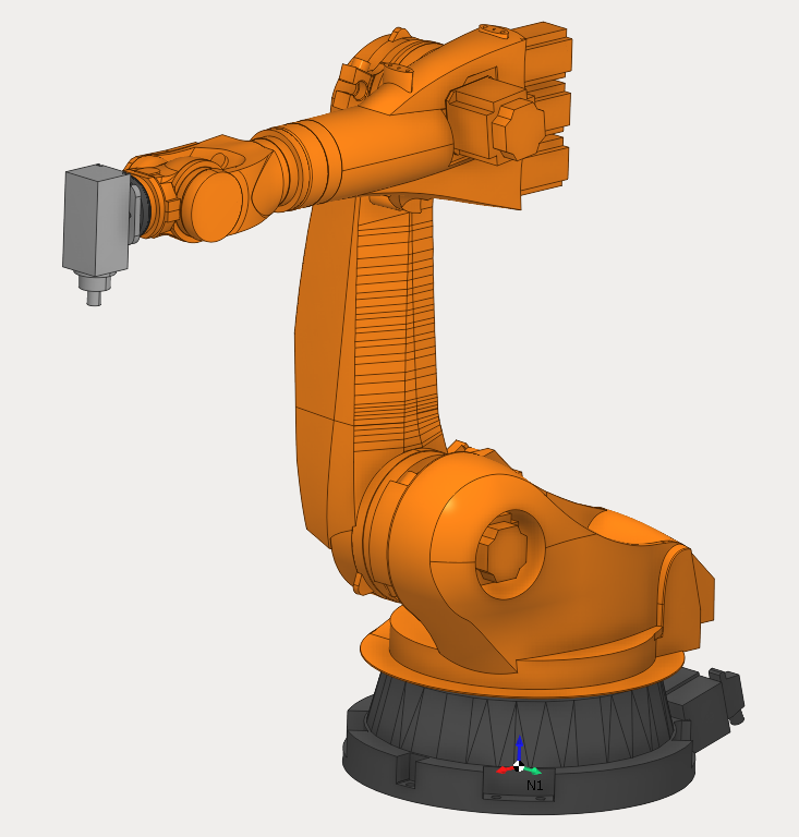
KUKA KR150 Industrial Robot with rotary table setup
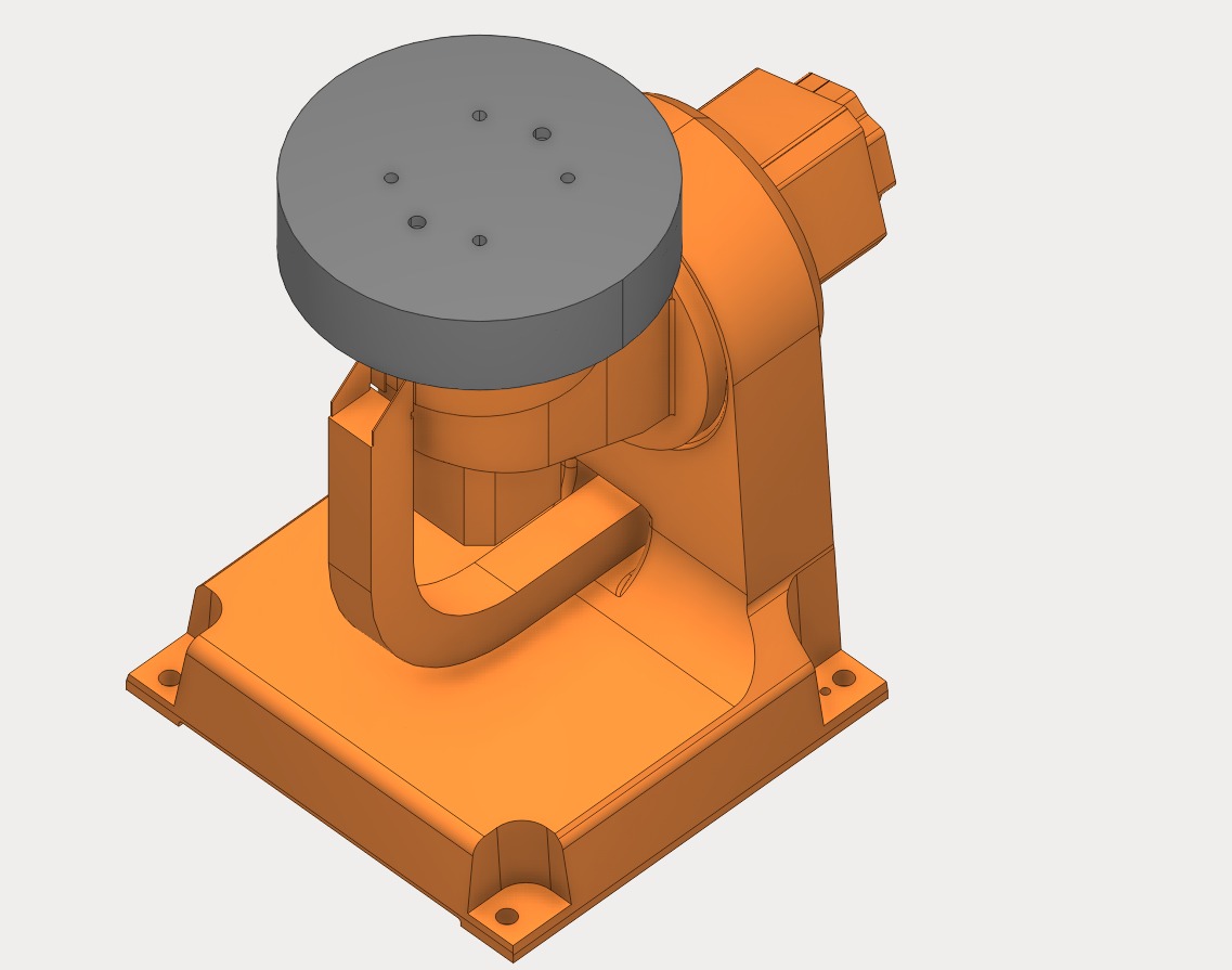
Rotary Table (4th Axis) - CNC Rotary Positioning Table
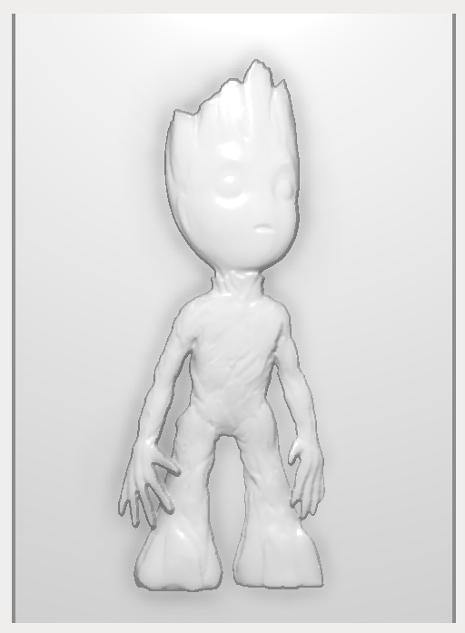
Expected Bas-Relief Carving Result