2-DOF Robotic Arm Parametric Trajectory
Implementation of inverse kinematics and trajectory planning for a 2-DOF planar robot arm to trace a complex geometric path, simulated in MATLAB/Simscape.
2-DOF Robotic Arm Parametric Trajectory
Overview
Implementation of inverse kinematics and trajectory planning for a 2-DOF planar robot arm to trace a complex geometric path, simulated in MATLAB/Simscape.
Project Overview
This project involves the kinematic analysis and simulation of a 2-Degree-of-Freedom (2-DOF) planar robotic manipulator. The primary objective was to design a control system capable of guiding the robot’s end-effector to trace a stylized clover shape defined by parametric equations.
The project demonstrates the application of Inverse Kinematics (IK) to map Cartesian task-space coordinates to the robot’s joint-space configuration, and uses MATLAB Simscape Multibody for high-fidelity physical simulation.
Mathematical Formulation
Path Generation
The target trajectory is a stylized three-leaf clover, mathematically defined in polar coordinates by the equation:
\[\rho = \frac{4+\cos(3(\theta -\gamma))}{10}\]Where $\rho$ is the radial distance and $\theta$ is the angle. This path is discretized and converted into Cartesian coordinates $(x, y)$ to serve as the reference setpoints for the robot.
Inverse Kinematics
To control the arm, we solved the inverse kinematics problem using geometric methods. For a given target position $(x, y)$, the required joint angles $q_1$ and $q_2$ were calculated. We considered both “Elbow Up” and “Elbow Down” configurations.
Using the Law of Cosines, the intermediate angle $\alpha$ is determined by:
\[\alpha = \arccos\left(\frac{l_1^2 + r^2 - l_2^2}{2 l_1 r}\right)\]where $l_1$ and $l_2$ are the link lengths ($l_1 = 0.22m, l_2 = 0.17m$) and $r$ is the distance from the base to the target.
Simulation & Results
The mathematical model was implemented in MATLAB to generate the joint trajectories. These trajectories were then fed into a Simscape Multibody model of the robot.
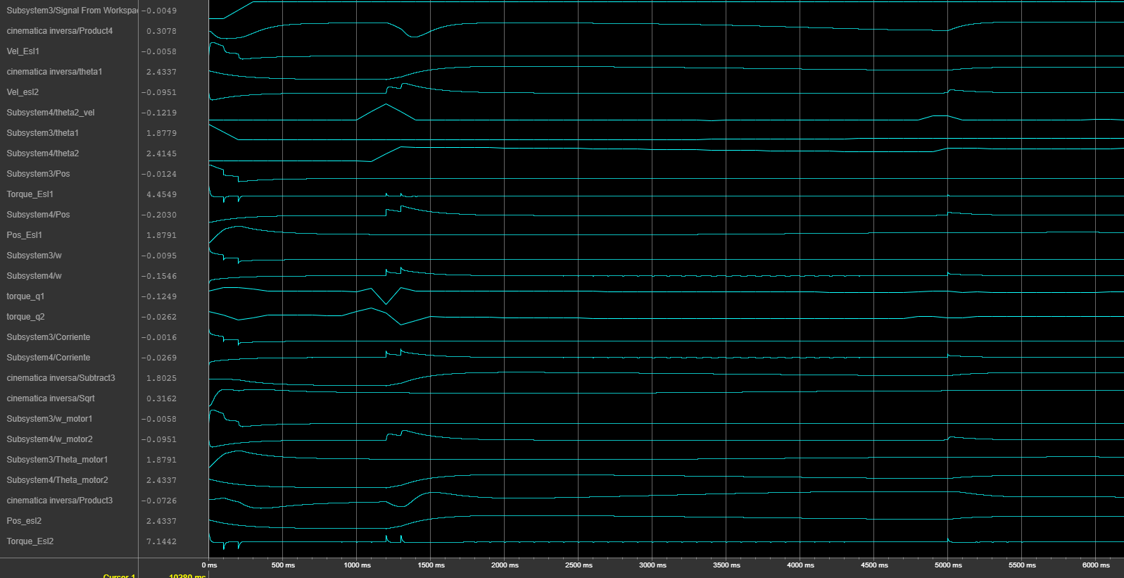
The simulation results confirmed the accuracy of the kinematic model. The plots (see right panel) show the resulting joint dynamics and the successful tracking of the Cartesian path.
Resources

Trajectory evolution animation
Simscape Multibody simulation of the arm tracing the target path

Generated Cartesian path (Stylized Clover)
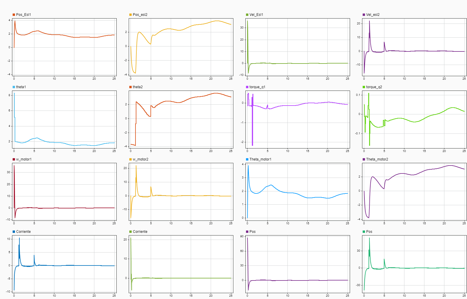
Simulink Data Inspector results
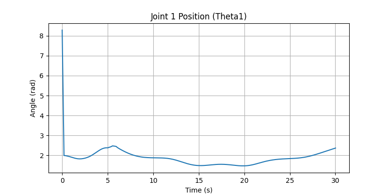
Joint 1 Angle (Theta 1) over time
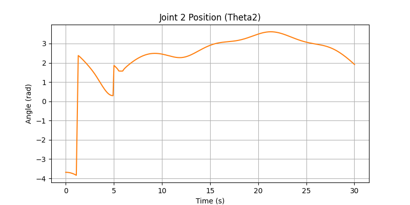
Joint 2 Angle (Theta 2) over time
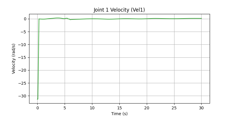
Joint 1 Velocity profile
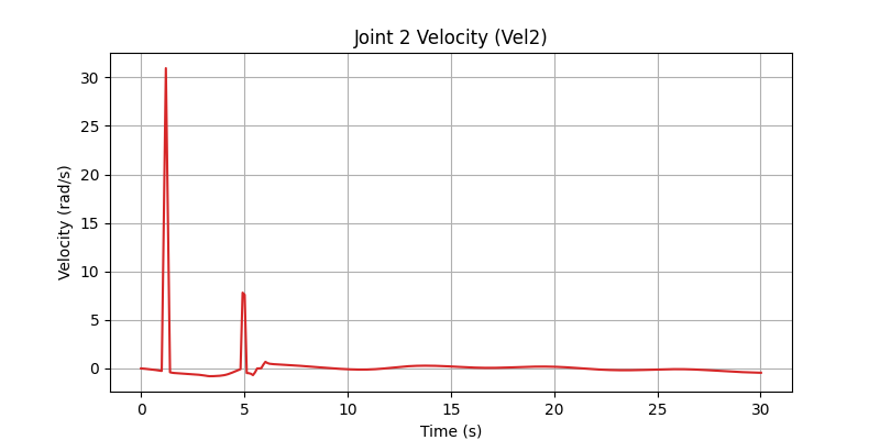
Joint 2 Velocity profile
Control Logic Analysis

Robot arm motion demonstration and testing