Electrical Panel Design: Star-Delta Motor Starter
Complete design and documentation of an industrial electrical panel for three-phase motor control using star-delta starting method, featuring 3D CAD modeling, electrical schematics, and component integration.
Electrical Panel Design: Star-Delta Motor Starter
Overview
Complete design and documentation of an industrial electrical panel for three-phase motor control using star-delta starting method, featuring 3D CAD modeling, electrical schematics, and component integration.
Project Overview
This project presents the complete design of an industrial electrical panel for controlling a 12 HP three-phase induction motor using the star-delta (Y-Δ) starting method. The star-delta configuration reduces inrush current during motor startup by initially connecting the motor windings in star configuration, then switching to delta configuration for normal operation.
The design encompasses electrical calculations, circuit schematics, component selection, 3D CAD modeling, and complete technical documentation following industrial standards.
Star-Delta Starting Method
Why Star-Delta?
When a three-phase induction motor starts directly (DOL - Direct On Line), it draws 6-8 times its rated current, causing:
- Voltage dips in the electrical network
- Mechanical stress on the motor and connected equipment
- High peak demand charges from utilities
The star-delta starter reduces starting current to approximately 1/3 of DOL starting current by:
- Star Connection (Y): Motor windings receive $\frac{V_L}{\sqrt{3}}$ voltage, reducing current
- Time Delay: Allows motor to accelerate (typically 5-15 seconds)
- Delta Connection (Δ): Full voltage applied for normal operation
Electrical Calculations
For a 12 HP motor at 120V line-to-neutral:
\[E_L = \sqrt{3} \times 120V = 207V\] \[I_L = \frac{12 \times 746W}{207V \times 0.77 \times \sqrt{3}} = 32.46A\] \[S = \sqrt{3} \times E_L \times I_L = 11,638VA = 11.638 kVA\]Control System Architecture
Contactor Arrangement
The system uses three ABB A40-30-10 contactors:
| Contactor | Function | Operation |
|---|---|---|
| KM1 | Main Line Contactor | Energized during both star and delta |
| KM2 | Star Contactor | Creates neutral point for star connection |
| KM3 | Delta Contactor | Connects windings in delta configuration |
Control Sequence
START pressed → KM1 + KM2 energize (Star)
     ↓
Timer delay (adjustable 5-15s)
     ↓
KM2 de-energizes, KM3 energizes (Delta)
     ↓
Motor runs at full speed
     ↓
STOP pressed → All contactors de-energize
Safety Features
- Mechanical & Electrical Interlocking between KM2 and KM3 (prevents simultaneous activation)
- ABB MS450 Motor Protection with overload and short-circuit protection
- Emergency Stop functionality via red push button
- Status Indication with pilot lights (green = running, yellow = starting)
3D CAD Design
The complete electrical panel was modeled in Autodesk Inventor Professional, featuring:
Component Integration
- All electrical components modeled with accurate dimensions
- Real manufacturer CAD data (ABB, Schneider Electric, Legrand)
- Wire routing using Cable & Harness module
- DIN rail mounting system
Enclosure Specifications
| Parameter | Value |
|---|---|
| Model | Schneider NSYS3D4320 |
| Dimensions | 400 × 300 × 200 mm |
| Material | Steel, RAL7035 finish |
| IP Rating | IP66 (dust-tight, water jets) |
| IK Rating | IK10 (20 joules impact) |
Internal Layout
The panel features organized component placement:
- Upper section: Circuit breakers and motor protection
- Middle section: Contactors and timer relays
- Lower section: Terminal blocks for field wiring
- Wire ducts: GARVIM 25×30mm for cable management
Electrical Schematics
Control Circuit
The control circuit includes:
- Start/Stop push buttons with maintained logic
- Timer relays for star-to-delta transition
- Auxiliary contacts for interlocking and status indication
- Overload relay contact for motor protection trip
Power Circuit
The power circuit handles:
- Three-phase power input through circuit breakers
- Motor starter protection via ABB MS450
- Contactor switching for star-delta configuration
- Six-wire motor connection (both ends of each winding accessible)
Bill of Materials
The complete BOM includes components from major industrial suppliers:
Control Components (Legrand)
- Push buttons (non-illuminated, green/red)
- Pilot indicators (24V, green/yellow)
- Timer relays (on-delay, adjustable)
- Miniature circuit breakers
Power Components (ABB)
- MS450 Manual Motor Starter (adjustable thermal overload)
- A40-30-10 Contactors (40A, 3-pole, 1NO auxiliary)
- HK1 Auxiliary Contact Blocks
Enclosure System (Schneider Electric)
- NSYS3D4320 Spacial S3D enclosure
- NSYDLM24 Modular DIN rail chassis
- NSYMB43 Mounting back plate
- NSYTRV62 Screw terminal blocks
Documentation Deliverables
The project includes complete technical documentation:
- Design Memory - Calculations, component selection rationale
- Power Circuit Diagram - Main circuit with contactor arrangement
- Control Circuit Diagram - Logic and interlocking circuits
- Terminal Block Diagrams - Field wiring reference (2 sheets)
- Panel Door Layout - Front panel component positions
- Equipment Disposition - Internal component arrangement
- Bill of Materials - Complete parts list with references
- 3D CAD Assembly - Full parametric model
Design Software
| Software | Purpose |
|---|---|
| Autodesk Inventor Professional | 3D CAD modeling, assembly, technical drawings |
| CadeSIMU | Electrical schematic design and simulation |
| Microsoft Excel | BOM management and calculations |
Skills Demonstrated
- Electrical Design: Motor control circuits, protection coordination
- 3D CAD Modeling: Complex assemblies, wire routing, technical documentation
- Industrial Standards: IEC/NEMA compliance, IP/IK ratings
- Component Selection: Matching specifications to application requirements
- Technical Documentation: Professional engineering deliverables
Applications
This star-delta starter design is suitable for:
- Industrial pumps and compressors (5-50 HP range)
- Conveyor systems with moderate starting torque
- HVAC equipment (fans, chillers)
- Manufacturing machinery requiring reduced starting current
The modular design allows adaptation to different motor ratings by selecting appropriate contactors and protection devices.
Components & Materials
| Component | Qty |
|---|---|
| Green Push Button | x1 |
| Red Push Button | x1 |
| Yellow Pilot Light | x1 |
| Green Pilot Light | x1 |
| Push Button Contact Block | x2 |
| Pilot Light Block | x2 |
| Timer Relay | x2 |
| Manual Motor Starter | x1 |
| Contactor | x3 |
| Auxiliary Contactor | x2 |
| Enclosure | x1 |
| DIN Rail Mount Chassis | x1 |
| Back Plate | x1 |
| Terminal Block | x11 |
| Wire Duct 25×30mm | x1 |
| Cable Gland PA | x2 |
| Circuit Breaker | x2 |
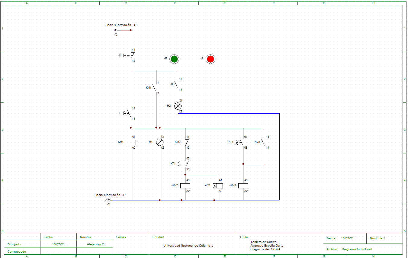
Electrical control circuit schematic for star-delta starting sequence
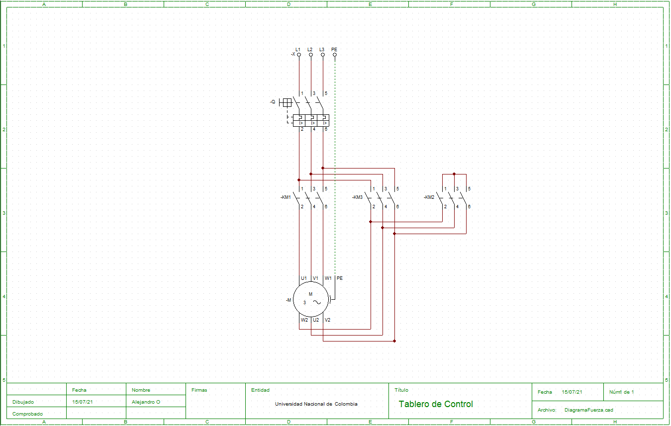
Main power circuit showing contactor arrangement for star-delta configuration